


1. Components Overview
49
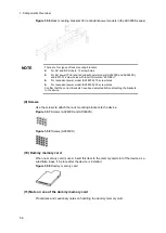
NOTE
Do not peel away the security tape. If you do so,
will be displayed. The
device is no longer under warranty if
is displayed.
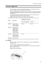
Figure 1-47
Back view
(1) Power supply unit slot 2
(2) Fan unit slot
(3) Ground terminal
(4) Power supply unit slot 1
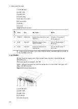
(2) Front panel
The front panel layout is shown in
Figure 1-48 Front panel layout
. The numbers in the
figure correspond to those in
Table 1-22 LED indications, switches and connectors
AX3830S-44XW supports the device sleep function and LED brightness control function
(power control (brightness) mode and off mode).
Figure 1-48
Front panel layout
Содержание AX2400S series
Страница 3: ...Copyright Copyright C 2005 2011 ALAXALA Networks Corporation All rights reserved ...
Страница 4: ......
Страница 6: ...Preface II Find description from the AX2400S series manuals ...
Страница 7: ...Preface III Find description from the AX3640S and AX3630S series manuals ...
Страница 10: ...Preface VI ...
Страница 14: ...Contents iv ...
Страница 160: ...3 Preparation of Interface Cables and Terminals 130 ...
Страница 214: ...4 Installation of the Components 184 ...
Страница 231: ...5 Expansion Replacement and Removal 201 Figure 5 18 Inserting the fan unit 1 Fan unit slot 2 Fan unit ...


