


4. Installation of the Components
135
NOTE
AX3830S and AX3650S series switches require space to insert or take out devices
above the memory card slot. When installing the Switch under another component,
ensure an appropriate amount of space, taking into consideration the component's
options and cables that stick out the front.
NOTE
The accessory rack mounting brackets are compatible with M5 screws. Use a rack
compatible with M5 screws.
NOTE
For rack-mounting conditions, see
[Step 1]
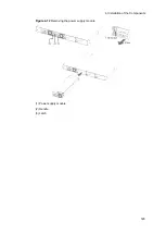
Attach the rack mounting brackets to the device.
Figure 4-2
Attaching the rack mounting brackets (AX2400S and AX3600S)
(1) Rack mounting bracket (L)
(2) Rack mounting bracket (R)
(3) M3 x 6 screws (12)
NOTE
The left bracket is marked with an "L", and the right with an "R".
Содержание AX2400S series
Страница 3: ...Copyright Copyright C 2005 2011 ALAXALA Networks Corporation All rights reserved ...
Страница 4: ......
Страница 6: ...Preface II Find description from the AX2400S series manuals ...
Страница 7: ...Preface III Find description from the AX3640S and AX3630S series manuals ...
Страница 10: ...Preface VI ...
Страница 14: ...Contents iv ...
Страница 160: ...3 Preparation of Interface Cables and Terminals 130 ...
Страница 214: ...4 Installation of the Components 184 ...
Страница 231: ...5 Expansion Replacement and Removal 201 Figure 5 18 Inserting the fan unit 1 Fan unit slot 2 Fan unit ...