


2. Preparation for Installation
105
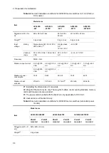
2.3.2 Electrical power equipment for 200 V AC
(1) AC power cable
Use the power cable described below.
Table 2-14
Specifications of AC power cable
Item
connector
on the Switch
Cable
Plug
for the outlet
Rating
10 A, 250 V
Japan PSE certified
10 A, 250 V
Japan PSE certified
10 A, 250 V
Japan PSE certified
Shape
Triplex
Prepare a plug that
suitable for the outlet.
(2) Electrical outlet
Use the electrical outlet described below. These electrical outlets are available at general
electrical contractors.
Two-pole grounded twist-locking receptacle: 10 A/250 V
Make sure to connect the AC model to a grounded outlet. Not connecting the
grounded outlet to the switch can cause electric shocks, as well as cause failures
due to electrical noise.
(3) Distribution board
The branch circuit to supply power to the Switch requires circuit breakers or other devices.
When selecting circuit breakers, make sure that they meet the following rating,
considering the input current and inrush current/time.
Breaker rating: 10 AT (single phase 200 V AC for a 10 A circuit) or less
For details about input current of the Switch, see
2.2.1 General installation conditions
, and
for details about inrush current and time of the Switch, see
Table 2-15
Inrush current
Series
model
Current (peak
value)
Time
AX2430S
AX2430S-24T
AX2430S-24T2X
40A
10 ms or less
AX2430S-48T
AX2430S-48T2X
50A
10 ms or less
AX3630S
AC model
#1
40A
10 ms or less
Redundant power model
40A
10 ms or less
AX3640S
AC model
40A
10 ms or less
Содержание AX2400S series
Страница 3: ...Copyright Copyright C 2005 2011 ALAXALA Networks Corporation All rights reserved ...
Страница 4: ......
Страница 6: ...Preface II Find description from the AX2400S series manuals ...
Страница 7: ...Preface III Find description from the AX3640S and AX3630S series manuals ...
Страница 10: ...Preface VI ...
Страница 14: ...Contents iv ...
Страница 160: ...3 Preparation of Interface Cables and Terminals 130 ...
Страница 214: ...4 Installation of the Components 184 ...
Страница 231: ...5 Expansion Replacement and Removal 201 Figure 5 18 Inserting the fan unit 1 Fan unit slot 2 Fan unit ...


