


1. Components Overview
66
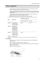
1.4 External power unit (EPU)
Connected via the special accessory cable, the external power unit (EPU) supplies
stand-by power to the main device of AX2400S and AX3600S series switches to configure
power redundancy, which allows continuous operation of the device without interruptions,
even if a failure occurs within the internal power unit. There are two types of EPUs:
EPU-A for AC models and EPU-B for AC (PoE) models. Available combination of the main
devices, EPUs and power supply modules are shown in
Table 1-34 Compatibility of main
devices with external power units (EPUs) and power supply modules
EPUs contain power supply modules. One power supply module can serve as the
stand-by power supply unit for one switch. By adding power supply modules to an EPU,
standby power can be supplied to up to four switches (EPU-A) (or two switches (EPU-B)).
Table 1-34
Compatibility of main devices with external power units (EPUs) and power
supply modules
Main Device
Compatible EPU
Compatible power
supply module
Power supply type
Model name
AC model
AX2430S-24T
AX2430S-24T2X
AX2430S-48T
AX2430S-48T2X
AX3630S-24T
AX3630S-24T2X
AX3640S-24T
EPU-A
EPU-AM
AC (PoE) model
AX3630S-24P
EPU-B
EPU-BM
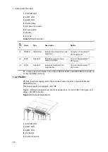
1.4.1 EPU-A
External power units for AC models are described below.
EPU-A has the following hardware specifications:
Power supply module slots: 4
Power supply module (EPU-AM): 1
NOTE
The EPU has one power supply module in slot 1. Blank panels over the other slots
when shipped.
Содержание AX2400S series
Страница 3: ...Copyright Copyright C 2005 2011 ALAXALA Networks Corporation All rights reserved ...
Страница 4: ......
Страница 6: ...Preface II Find description from the AX2400S series manuals ...
Страница 7: ...Preface III Find description from the AX3640S and AX3630S series manuals ...
Страница 10: ...Preface VI ...
Страница 14: ...Contents iv ...
Страница 160: ...3 Preparation of Interface Cables and Terminals 130 ...
Страница 214: ...4 Installation of the Components 184 ...
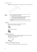
Страница 231: ...5 Expansion Replacement and Removal 201 Figure 5 18 Inserting the fan unit 1 Fan unit slot 2 Fan unit ...


