110
6000 Series Oscilloscope User’s Guide
3
Viewing and Measuring Digital Signals
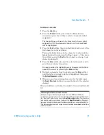
To connect the digital probes to the circuit under test
The digital channels are enabled on MSO6000 models and
DSO6000 models which have the MSO upgrade license installed.
1
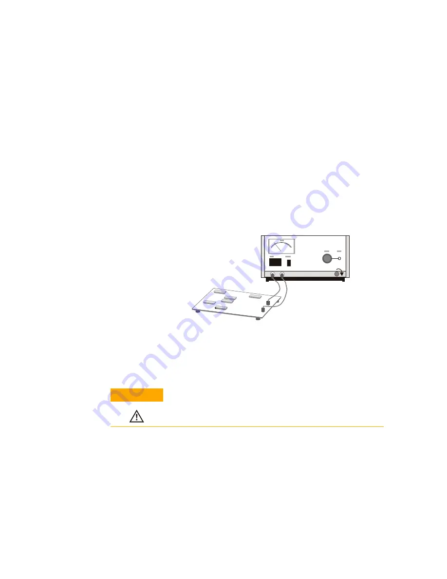
If you feel it’s necessary, turn off the power supply to the
circuit under test.
Turning off power to the circuit under test would only
prevent damage that might occur if you accidentally short
two lines together while connecting probes. You can leave the
oscilloscope powered on because no voltage appears at the
probes.
2
Connect the digital probe cable to the D15 - D0 connector on
the rear panel of the mixed-signal oscilloscope. The digital
probe cable is indexed so you can connect it only one way.
You do not need to power-off the oscilloscope.
3
Route the cable under the oscilloscope and bring it out in
front. Lay the two sections of the digital cable on top of each
other at the front of the oscilloscope. Slip the narrow end of
the cable guide over the cable and into its slots at the front of
Off
C A U T I O N
Use only the Agilent part number 54620-68701 digital probe kit
supplied with the mixed-signal oscilloscope.
Содержание InfiniiVision DSO6014L
Страница 2: ...Agilent Technologies Agilent 6000 Series Oscilloscopes User s Guide...
Страница 59: ...58 6000 Series Oscilloscope User s Guide 1 Getting Started...
Страница 109: ...108 6000 Series Oscilloscope User s Guide 2 Front Panel Controls...
Страница 125: ...124 6000 Series Oscilloscope User s Guide 3 Viewing and Measuring Digital Signals...
Страница 251: ...250 6000 Series Oscilloscope User s Guide 5 Making Measurements...
Страница 287: ...286 6000 Series Oscilloscope User s Guide 6 Displaying Data Interpreting Decoded LIN Data...
Страница 321: ...320 6000 Series Oscilloscope User s Guide 7 Saving and Printing Data...
Страница 370: ......


