Chapter 2: Setting Up the Oscilloscope
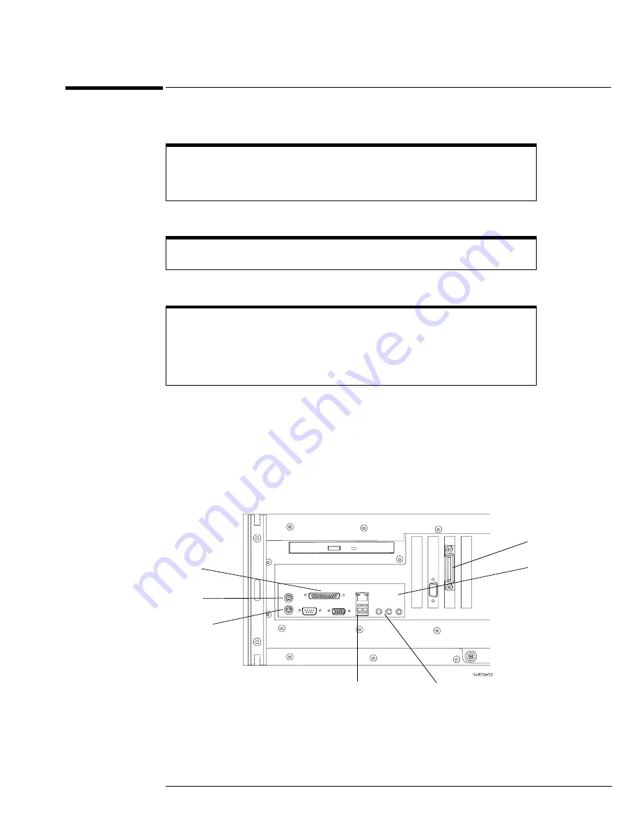
To connect the mouse, keyboard, LAN, printer, and GPIB cable
23
To connect the mouse, keyboard, LAN, printer, and GPIB cable
Mouse. Plug the mouse into the mouse connector on the rear panel of the oscilloscope.
Keyboard. Plug the keyboard cable into the keyboard connector on the rear panel of the oscilloscope.
LAN Cable. Connect your LAN cable to the RJ-45 connector on the rear panel of the oscilloscope.
Printer Cable. If you have a USB printer, you will need to connect its cable to one of the four USB ports on the
rear panel, or to the USB port on the front panel.
If you have a parallel printer, you will need to connect its parallel printer cable to the Parallel
Printer connector on the oscilloscope.
GPIB Cable. If you will be controlling the oscilloscope through the GPIB, attach your GPIB cable to the GPIB
connector on the rear of the oscilloscope.
Figure 2-5
Rear Panel
Note:
Your instrument’s rear panel configuration may differ from this diagram. Connect the cables based on your instrument’s
configuration.
While you can operate many oscilloscope functions using only the front-panel keys and
knobs, you will need the mouse to access advanced oscilloscope functions through the
graphical interface, or to find out more about the oscilloscope through the built-in
information system.
A keyboard must be plugged into the oscilloscope before the Windows operating system
has started booting.
Depending on your building’s LAN configuration, you may need to set up the
oscilloscope’s network configuration after connecting the LAN cable to the
oscilloscope. If your building’s network uses DHCP, many parameters will already be
compatible. Before you set up the network configuration, you should exit the
oscilloscope application. If you do not know how to setup the network, see your network
administrator or use the Windows XP on-line help.
Mouse
Keyboard
USB
Ports
GPIB
LAN
Parallel
Printer
Line In
Line Out
Microphone
Содержание DSO80204B
Страница 7: ...6...
Страница 17: ...Chapter 1 General Information Oscilloscope Dimensions 16...
Страница 34: ...3 To run the self calibration 35 Calibration...
Страница 35: ...34 Calibration This chapter provides self calibration procedures for the oscilloscope...
Страница 92: ...Chapter 5 Troubleshooting Motherboard Verification 91 Figure 5 14 Sense cable...
Страница 140: ...Chapter 7 Replaceable Parts Exploded Views 139 Exploded Views Front Frame and Front Panel...
Страница 141: ...Chapter 7 Replaceable Parts Exploded Views 140 Fan and Acquisition Assembly...
Страница 142: ...Chapter 7 Replaceable Parts Exploded Views 141 Power Supply and PC Motherboard...
Страница 143: ...Chapter 7 Replaceable Parts Exploded Views 142 Sleeve and Accessory Pouch...
Страница 149: ...Chapter 8 Theory of Operation 148 Figure 8 1 Oscilloscope Block Diagram...
Страница 157: ...156...
Страница 159: ...158 Index...


