


75
T
est
P
at
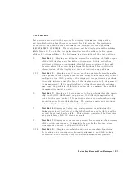
10.
Displays
an
H
pattern
for
checking
the
focus
of
the
display
.
Under
normal
conditions
,
this
should
never
need
to
be
adjusted.
However
,
it
is
possible
to
adjust
it
by
accessing
the
focus
control
adjustment
at
the
left
rear
of
the
display
.
See
the
\A
djustments"
chapter
.
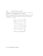
76
T
est
P
at
11.
V
eries
the
functionality
of
the
pixel
stretching
circuit
of
the
A19
GSP
board.
Under
normal
conditions
,
this
pattern
should
appear
all
white
.
If
a
failure
occurs
in
the
pixel
stretching
circuit,
the
pattern
will
consist
of
16
alternating
white
and
gray
vertical
stripes
.
Suspect
problems
with
the
STRETCH
line
and
LFIRSTPIX.
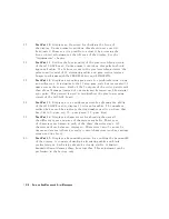
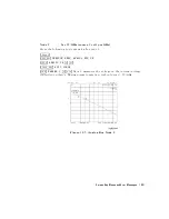
77
T
est
P
at
12.
Displays
a
repeating
gray
scale
for
troubleshooting,
using
an
oscilloscope
.
It
is
similar
to
the
16
step
gray
scale
but
is
repeated
32
times
across
the
screen.
Each
of
the
3
outputs
of
the
video
palette
will
then
show
32
ramps
(instead
of
one
staircase)
between
each
horizontal
sync
pulse
.
This
pattern
is
used
to
troubleshoot
the
pixel
processing
circuit
of
the
A19
GSP
board.
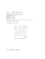
78
T
est
P
at
13.
Displays
a
color
rainbow
pattern
for
showing
the
ability
of
the
A19
GSP
board
to
display
15
colors
plus
white
.
The
numbers
written
below
each
bar
indicate
the
tint
number
used
to
produce
that
bar
(0
&
100=pure
red,
33=pure
green,
67=pure
blue).
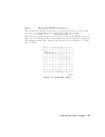
79
T
est
P
at
14.
Displays
a
character
set
for
showing
the
user
all
the
dierent
types
and
sizes
of
characters
available
.
Three
sets
of
characters
are
drawn
in
each
of
the
three
character
sizes
.
125
characters
of
each
size
are
displayed.
Characters
0
and
3
cannot
be
drawn
and
several
others
are
really
control
characters
(such
as
carriage
return
and
line
feed).
80
T
est
P
at
15.
Displays
a
bandwidth
pattern
for
verifying
the
bandwidth
of
the
display
.
It
consists
of
multiple
alternating
white
and
black
vertical
stripes
.
Each
stripe
should
be
clearly
visible
.
A
limited
bandwidth
would
smear
these
lines
together
.
This
adjustment
can
be
performed
in
the
factory
only
.
10-18
Service
K
ey
Menus
and
Error
Messages
Содержание 8752C
Страница 22: ...Before Applying Power 15 6 Servicing 15 6 Index Contents 16 ...
Страница 38: ......
Страница 43: ...Figure 2 1 Measurement Uncertainty Window System Veri cation and Performance Tests 2 5 ...
Страница 80: ...Figure 2 15 Magnitude Dynamic Accuracy Test Setup 2 42 System Veri cation and Performance Tests ...
Страница 116: ......
Страница 122: ...Figure 3 1 Location of Major Assemblies 3 6 Adjustments and Correction Constants ...
Страница 176: ......
Страница 192: ...4 16 Start Troubleshooting Here ...
Страница 193: ......
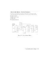
Страница 194: ...Figure 4 7 HP 8752C Overall Block Diagram 2 of 4 Option 003 and 004 Start Troubleshooting Here 4 19 ...
Страница 195: ...Figure 4 7 HP 8752C Overall Block Diagram 3 of 4 Option 006 4 20 Start Troubleshooting Here ...
Страница 196: ...Figure 4 7 HP 8752C Overall Block Diagram 4 of 4 Option 004 and 006 Start Troubleshooting Here 4 21 ...
Страница 197: ......
Страница 221: ...5 24 Power Supply Troubleshooting ...
Страница 222: ......
Страница 225: ...Digital Control Group Block Diagram Figure 6 1 Digital Control Group Block Diagram Digital Control Troubleshooting 6 3 ...
Страница 267: ...Figure 7 18 25 MHz HI OUT Waveform from A14J1 Figure 7 19 60 MHz HI OUT Waveform from A14J1 Source Troubleshooting 7 27 ...
Страница 271: ...Figure 7 21 A14 Generated Digital Control Signals Source Troubleshooting 7 31 ...
Страница 301: ...Figure 9 2 Typical Smith Chart Traces of Good Short a and Open b Accessories Troubleshooting 9 7 ...
Страница 302: ......
Страница 366: ......
Страница 378: ...Figure 11 4 Typical ED Re ection Test Port 11 12 Error Terms ...
Страница 380: ...Figure 11 5 Typical ES Re ection Test Port 11 14 Error Terms ...
Страница 382: ...Figure 11 6 Typical ER Re ection Test Port 11 16 Error Terms ...
Страница 384: ...Figure 11 7 Typical EX with 10 Hz Bandwidth Figure 11 8 Typical EX with 3 kHz Bandwidth 11 18 Error Terms ...
Страница 386: ...Figure 11 9 Typical ET 11 20 Error Terms ...
Страница 407: ...Figure 12 5 High Band Operation of the Source Theory of Operation 12 21 ...
Страница 410: ...Figure 12 6 Receiver Functional Group standard and Option 003 12 24 Theory of Operation ...
Страница 411: ...Figure 12 7 Receiver Functional Group Option 003 and 004 Theory of Operation 12 25 ...
Страница 412: ...Figure 12 8 Receiver Functional Group Option 006 12 26 Theory of Operation ...
Страница 413: ...Figure 12 9 Receiver Functional Group Option 004 and 006 Theory of Operation 12 27 ...
Страница 416: ......
Страница 419: ...Figure 13 1 Module Exchange Procedure Replaceable Parts 13 3 ...
Страница 423: ...Major Assemblies Replaceable Parts 13 7 ...
Страница 425: ...Front Panel Assemblies Replaceable Parts 13 9 ...
Страница 427: ...Rear Panel Assemblies Replaceable Parts 13 11 ...
Страница 429: ...Cables Top View Replaceable Parts 13 13 ...
Страница 431: ...Front Panel Cables and Attaching Hardware Replaceable Parts 13 15 ...
Страница 433: ...Rear Panel Cables and Attaching Hardware Replaceable Parts 13 17 ...
Страница 435: ...Source and Sampler Parts Standard and Option 003 Replaceable Parts 13 19 ...
Страница 437: ...Source and Sampler Parts Option 004 006 Replaceable Parts 13 21 ...
Страница 439: ...Source and Sampler Parts Options 004 and 003 004 Replaceable Parts 13 23 ...
Страница 441: ...Source and Sampler Parts Option 006 Replaceable Parts 13 25 ...
Страница 443: ...Display Bezel Assembly Replaceable Parts 13 27 ...
Страница 445: ...Chassis Parts Replaceable Parts 13 29 ...
Страница 447: ...Top View of Attaching Hardware and Post Regulator Fuses Replaceable Parts 13 31 ...
Страница 449: ...Bottom View of Attaching Hardware Replaceable Parts 13 33 ...
Страница 488: ......