


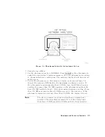

Note
If
you
have
replaced
the
CPU
board,
or
if
the
analyzer
has
lost
all
of
its
correction
constants
perform
the
adjustments
in
the
order
listed
below
(from
top
to
bottom):
1.
A9
CC
Jumper
P
osition
Procedure
12.
Serial
Number
Correction
Constant
(T
est
#55)
13.
Option
Number
Correction
Constant
(T
est
#56)
16.
Model
Number
Correction
Constant
14.
Initialize
EEPROMs
(T
est
#58)
16.
Model
Number
Correction
Constant
7.
Display
Intensity
A
djustments
(T
est
#49)
17.
V
ertical
P
osition
and
F
ocus
A
djustments
18.
Display
Degaussing
(Demagnetizing)
2.
Source
Default
Correction
Constants
(T
est
#44)
3.
Source
Pretune
Default
Correction
Constants
(T
est
#45)
4.
Analog
Bus
Correction
Constants
(T
est
#46)
9.
ADC
Oset
Correction
Constants
(T
est
#52)
19.
Fractional-N
Frequency
Range
A
djustment
6.
Source
Pretune
Correction
Constants
(T
est
#48)
20.
Frequency
A
ccuracy
A
djustment
21.
High/Low
Band
Transition
A
djustment
22.
Fractional-N
Spur
and
FM
Sideband
A
djustment
23.
Source
Spur
A
voidance
Tracking
A
djustment
5.
RF
Output
P
ower
Correction
Constants
(T
est
#47)
8.
IF
Amplier
Correction
Constants
(T
est
#51)
11.
Cavity
Oscillator
Correction
Constants
(T
est
#54)
10.
Frequency
Response
Correction
Constants
(T
ests
#57
then
#53)
15.
EEPROM
Backup
Disk
Procedure
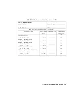
T
est
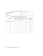
Equipment
Specications
Each
of
the
following
procedures
lists
the
equipment
required
to
perform
the
adjustment
procedure
.
Typically
,
common
hand
tools
(screwdrivers
,
etc
.)
are
not
listed.
If
you
do
not
have
the
required
equipment,
refer
to
the
critical
specications
in
T
able
1-1
to
identify
appropriate
substitutes
.
Adjustments
and
Correction
Constants
3-3
Содержание 8752C
Страница 22: ...Before Applying Power 15 6 Servicing 15 6 Index Contents 16 ...
Страница 38: ......
Страница 43: ...Figure 2 1 Measurement Uncertainty Window System Veri cation and Performance Tests 2 5 ...
Страница 80: ...Figure 2 15 Magnitude Dynamic Accuracy Test Setup 2 42 System Veri cation and Performance Tests ...
Страница 116: ......
Страница 122: ...Figure 3 1 Location of Major Assemblies 3 6 Adjustments and Correction Constants ...
Страница 176: ......
Страница 192: ...4 16 Start Troubleshooting Here ...
Страница 193: ......
Страница 194: ...Figure 4 7 HP 8752C Overall Block Diagram 2 of 4 Option 003 and 004 Start Troubleshooting Here 4 19 ...
Страница 195: ...Figure 4 7 HP 8752C Overall Block Diagram 3 of 4 Option 006 4 20 Start Troubleshooting Here ...
Страница 196: ...Figure 4 7 HP 8752C Overall Block Diagram 4 of 4 Option 004 and 006 Start Troubleshooting Here 4 21 ...
Страница 197: ......
Страница 221: ...5 24 Power Supply Troubleshooting ...
Страница 222: ......
Страница 225: ...Digital Control Group Block Diagram Figure 6 1 Digital Control Group Block Diagram Digital Control Troubleshooting 6 3 ...
Страница 267: ...Figure 7 18 25 MHz HI OUT Waveform from A14J1 Figure 7 19 60 MHz HI OUT Waveform from A14J1 Source Troubleshooting 7 27 ...
Страница 271: ...Figure 7 21 A14 Generated Digital Control Signals Source Troubleshooting 7 31 ...
Страница 301: ...Figure 9 2 Typical Smith Chart Traces of Good Short a and Open b Accessories Troubleshooting 9 7 ...
Страница 302: ......
Страница 366: ......
Страница 378: ...Figure 11 4 Typical ED Re ection Test Port 11 12 Error Terms ...
Страница 380: ...Figure 11 5 Typical ES Re ection Test Port 11 14 Error Terms ...
Страница 382: ...Figure 11 6 Typical ER Re ection Test Port 11 16 Error Terms ...
Страница 384: ...Figure 11 7 Typical EX with 10 Hz Bandwidth Figure 11 8 Typical EX with 3 kHz Bandwidth 11 18 Error Terms ...
Страница 386: ...Figure 11 9 Typical ET 11 20 Error Terms ...
Страница 407: ...Figure 12 5 High Band Operation of the Source Theory of Operation 12 21 ...
Страница 410: ...Figure 12 6 Receiver Functional Group standard and Option 003 12 24 Theory of Operation ...
Страница 411: ...Figure 12 7 Receiver Functional Group Option 003 and 004 Theory of Operation 12 25 ...
Страница 412: ...Figure 12 8 Receiver Functional Group Option 006 12 26 Theory of Operation ...
Страница 413: ...Figure 12 9 Receiver Functional Group Option 004 and 006 Theory of Operation 12 27 ...
Страница 416: ......
Страница 419: ...Figure 13 1 Module Exchange Procedure Replaceable Parts 13 3 ...
Страница 423: ...Major Assemblies Replaceable Parts 13 7 ...
Страница 425: ...Front Panel Assemblies Replaceable Parts 13 9 ...
Страница 427: ...Rear Panel Assemblies Replaceable Parts 13 11 ...
Страница 429: ...Cables Top View Replaceable Parts 13 13 ...
Страница 431: ...Front Panel Cables and Attaching Hardware Replaceable Parts 13 15 ...
Страница 433: ...Rear Panel Cables and Attaching Hardware Replaceable Parts 13 17 ...
Страница 435: ...Source and Sampler Parts Standard and Option 003 Replaceable Parts 13 19 ...
Страница 437: ...Source and Sampler Parts Option 004 006 Replaceable Parts 13 21 ...
Страница 439: ...Source and Sampler Parts Options 004 and 003 004 Replaceable Parts 13 23 ...
Страница 441: ...Source and Sampler Parts Option 006 Replaceable Parts 13 25 ...
Страница 443: ...Display Bezel Assembly Replaceable Parts 13 27 ...
Страница 445: ...Chassis Parts Replaceable Parts 13 29 ...
Страница 447: ...Top View of Attaching Hardware and Post Regulator Fuses Replaceable Parts 13 31 ...
Страница 449: ...Bottom View of Attaching Hardware Replaceable Parts 13 33 ...
Страница 488: ......