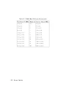


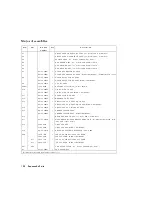

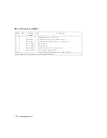

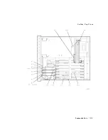


Major
Assemblies
Item
Opt.
HP
P
art
Number
Qty
Description
A1
FRONT
P
ANEL
KEYBO
ARD
ASSY
(see
\Front
P
anel
Assemblies")
A2
FRONT
P
ANEL
INTERF
A
CE
ASSY
(see
\Front
P
anel
Assemblies")
A3
SOURCE
ASSY
(see
\Source
and
Sampler
P
arts")
A4
R
SAMPLER
ASSY
(see
\Source
and
Sampler
P
arts")
A5
A
SAMPLER
ASSY
(see
\Source
and
Sampler
P
arts")
A6
B
SAMPLER
ASSY
(see
\Source
and
Sampler
P
arts")
A7
08753-60007
1
PULSE
GENERA
TOR
BD
ASSY
08753-69007
PULSE
GENERA
TOR
BD
ASSY
(Rebuilt-Exchange)
(includes
board
cover)
A8
08753-60208
1
POST
REGULA
TOR
BD
ASSY
08753-69208
POST
REGULA
TOR
BD
ASSY
(Rebuilt-Exchange)
A9
08752-60016
1
CPU
BD
ASSY
A9BT1
1420-0394
1
B
A
TTERY-LITHIUM
3V
1A
(not
shown)
A10
08753-60095
1
DIGIT
AL
IF
BD
ASSY
08753-69095
DIGIT
AL
IF
BD
ASSY
(Rebuilt-Exchange)
A11
08753-60162
1
PHASE
LOCK
BD
ASSY
A12
08752-60023
1
REFERENCE
BD
ASSY
A13
08753-60013
1
FRA
CTIONAL-N
ANALOG
BD
ASSY
08753-69013
FRA
CTIONAL-N
ANALOG
BD
ASSY
(Rebuilt-Exchange)
A14
08753-60068
1
FRA
CTIONAL-N
DIGIT
AL
BD
ASSY
A15
08753-60098
1
PREREGULA
TOR
ASSY
08753-69098
PREREGULA
TOR
ASSY
(Rebuilt-Exchange)
A16
REAR
P
ANEL
BD
ASSY
(see
\Rear
P
anel
Assemblies")
A17
08753-60130
1
MOTHERBO
ARD
ASSY
REPLA
CEMENT
KIT
(includes
motherboard,
card
cage
,
and
corner
struts)
A18
2090-0210
1
DISPLA
Y
ASSY
5180-8484
DISPLA
Y
ASSY
(Rebuilt-Exchange)
A19
08753-60170
1
GRAPHICS
SYSTEM
PROCESSOR
(GSP)
ASSY
A30
5086-7955
1
50
DU
AL
DIRECTIONAL
COUPLER*
5086-6955
50
COUPLER*
(Rebuilt-Exchange)
075
5086-7557
1
75
DU
AL
DIRECTIONAL
COUPLER*
075
5086-6557
75
COUPLER*
(Rebuilt-Exchange)
A
T1
006
8
dB
A
TTENU
A
TOR
(see
\Source
and
Sampler
P
arts")
B1
08753-60047
1
F
AN
ASSEMBL
Y
*includes
bracket
and
front
panel
connectors
13-6
Replaceable
Parts
Содержание 8752C
Страница 22: ...Before Applying Power 15 6 Servicing 15 6 Index Contents 16 ...
Страница 38: ......
Страница 43: ...Figure 2 1 Measurement Uncertainty Window System Veri cation and Performance Tests 2 5 ...
Страница 80: ...Figure 2 15 Magnitude Dynamic Accuracy Test Setup 2 42 System Veri cation and Performance Tests ...
Страница 116: ......
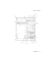
Страница 122: ...Figure 3 1 Location of Major Assemblies 3 6 Adjustments and Correction Constants ...
Страница 176: ......
Страница 192: ...4 16 Start Troubleshooting Here ...
Страница 193: ......
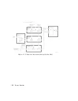
Страница 194: ...Figure 4 7 HP 8752C Overall Block Diagram 2 of 4 Option 003 and 004 Start Troubleshooting Here 4 19 ...
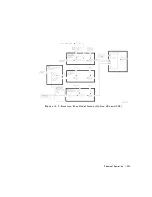
Страница 195: ...Figure 4 7 HP 8752C Overall Block Diagram 3 of 4 Option 006 4 20 Start Troubleshooting Here ...
Страница 196: ...Figure 4 7 HP 8752C Overall Block Diagram 4 of 4 Option 004 and 006 Start Troubleshooting Here 4 21 ...
Страница 197: ......
Страница 221: ...5 24 Power Supply Troubleshooting ...
Страница 222: ......
Страница 225: ...Digital Control Group Block Diagram Figure 6 1 Digital Control Group Block Diagram Digital Control Troubleshooting 6 3 ...
Страница 267: ...Figure 7 18 25 MHz HI OUT Waveform from A14J1 Figure 7 19 60 MHz HI OUT Waveform from A14J1 Source Troubleshooting 7 27 ...
Страница 271: ...Figure 7 21 A14 Generated Digital Control Signals Source Troubleshooting 7 31 ...
Страница 301: ...Figure 9 2 Typical Smith Chart Traces of Good Short a and Open b Accessories Troubleshooting 9 7 ...
Страница 302: ......
Страница 366: ......
Страница 378: ...Figure 11 4 Typical ED Re ection Test Port 11 12 Error Terms ...
Страница 380: ...Figure 11 5 Typical ES Re ection Test Port 11 14 Error Terms ...
Страница 382: ...Figure 11 6 Typical ER Re ection Test Port 11 16 Error Terms ...
Страница 384: ...Figure 11 7 Typical EX with 10 Hz Bandwidth Figure 11 8 Typical EX with 3 kHz Bandwidth 11 18 Error Terms ...
Страница 386: ...Figure 11 9 Typical ET 11 20 Error Terms ...
Страница 407: ...Figure 12 5 High Band Operation of the Source Theory of Operation 12 21 ...
Страница 410: ...Figure 12 6 Receiver Functional Group standard and Option 003 12 24 Theory of Operation ...
Страница 411: ...Figure 12 7 Receiver Functional Group Option 003 and 004 Theory of Operation 12 25 ...
Страница 412: ...Figure 12 8 Receiver Functional Group Option 006 12 26 Theory of Operation ...
Страница 413: ...Figure 12 9 Receiver Functional Group Option 004 and 006 Theory of Operation 12 27 ...
Страница 416: ......
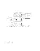
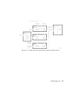
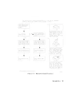
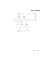
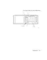
Страница 419: ...Figure 13 1 Module Exchange Procedure Replaceable Parts 13 3 ...
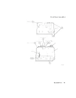
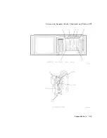
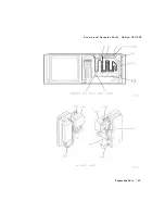
Страница 423: ...Major Assemblies Replaceable Parts 13 7 ...
Страница 425: ...Front Panel Assemblies Replaceable Parts 13 9 ...
Страница 427: ...Rear Panel Assemblies Replaceable Parts 13 11 ...
Страница 429: ...Cables Top View Replaceable Parts 13 13 ...
Страница 431: ...Front Panel Cables and Attaching Hardware Replaceable Parts 13 15 ...
Страница 433: ...Rear Panel Cables and Attaching Hardware Replaceable Parts 13 17 ...
Страница 435: ...Source and Sampler Parts Standard and Option 003 Replaceable Parts 13 19 ...
Страница 437: ...Source and Sampler Parts Option 004 006 Replaceable Parts 13 21 ...
Страница 439: ...Source and Sampler Parts Options 004 and 003 004 Replaceable Parts 13 23 ...
Страница 441: ...Source and Sampler Parts Option 006 Replaceable Parts 13 25 ...
Страница 443: ...Display Bezel Assembly Replaceable Parts 13 27 ...
Страница 445: ...Chassis Parts Replaceable Parts 13 29 ...
Страница 447: ...Top View of Attaching Hardware and Post Regulator Fuses Replaceable Parts 13 31 ...
Страница 449: ...Bottom View of Attaching Hardware Replaceable Parts 13 33 ...
Страница 488: ......