


A
djustment
T
ests
The
tests
without
asterisks
are
used
in
the
procedures
located
in
the
\A
djustments"
chapter
of
this
manual,
except
as
noted.
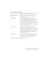
44
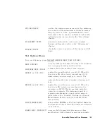
*Source
Def.
Writes
default
correction
constants
for
rudimentary
source
power
accuracy
.
Use
this
test
before
running
test
47,
below
.
45
*Pretune
Def.
Writes
default
correction
constants
for
rudimentary
phase
lock
pretuning
accuracy
.
Use
this
test
before
running
test
48,
below
.
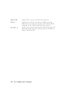
46
ABUS
Cor
.
Measures
three
xed
voltages
on
the
ABUS,
and
generates
new
correction
constants
for
ABUS
amplitude
accuracy
in
both
high
resolution
and
low
resolution
modes
.
Use
this
test
before
running
test
48,
below
.
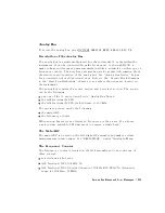
47
Source
Cor
.
Measures
source
output
power
accuracy
,
atness
,
and
linearity
against
an
external
power
meter
via
HP-IB
to
generate
new
correction
constants
.
Run
tests
44,
45,
46,
and
48
rst.
48
Pretune
Cor
.
Generates
source
pretune
values
for
proper
phase-locked
loop
operation.
Run
tests
44,
45,
and
46
rst.
49
Intensity
Cor
.
Stores
the
current
values
of
the
intensity
adjustments
under
4
DISPLA
Y
5
for
recall
of
display
intensity
values
at
power-on.
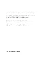
50
Disp
2
Ex.
Not
used
in
\A
djustments
."
Writes
the
\secondary
test
pattern"
to
the
display
for
adjustments
.
Press
4
PRESET
5
to
exit
this
routine
.
51
IF
Step
Cor
.
Measures
the
gain
of
the
IF
ampliers
(A
and
B
only)
located
on
the
A10
digital
IF
,
to
determine
the
correction
constants
for
absolute
amplitude
accuracy
.
It
provides
smooth
dynamic
accuracy
and
absolute
amplitude
accuracy
in
the
030
dBm
input
power
region.
52
ADC
Ofs
Cor
.
Measures
the
A10
Digital
IF
ADC
linearity
characteristics
,
using
an
internal
ramp
generator
,
and
stores
values
for
the
optimal
operating
region.
During
measurement,
IF
signals
are
centered
in
the
optimal
region
to
improve
low-level
dynamic
accuracy
.
53
Sampler
Cor
.
Measures
the
absolute
amplitude
response
of
the
R
sampler
against
an
external
power
meter
via
HP-IB
,
then
compares
A
and
B
,
(magnitude
and
phase),
against
R.
It
improves
the
R
input
accuracy
and
A/B/R
tracking.
10-14
Service
K
ey
Menus
and
Error
Messages
Содержание 8752C
Страница 22: ...Before Applying Power 15 6 Servicing 15 6 Index Contents 16 ...
Страница 38: ......
Страница 43: ...Figure 2 1 Measurement Uncertainty Window System Veri cation and Performance Tests 2 5 ...
Страница 80: ...Figure 2 15 Magnitude Dynamic Accuracy Test Setup 2 42 System Veri cation and Performance Tests ...
Страница 116: ......
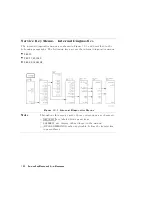
Страница 122: ...Figure 3 1 Location of Major Assemblies 3 6 Adjustments and Correction Constants ...
Страница 176: ......
Страница 192: ...4 16 Start Troubleshooting Here ...
Страница 193: ......
Страница 194: ...Figure 4 7 HP 8752C Overall Block Diagram 2 of 4 Option 003 and 004 Start Troubleshooting Here 4 19 ...
Страница 195: ...Figure 4 7 HP 8752C Overall Block Diagram 3 of 4 Option 006 4 20 Start Troubleshooting Here ...
Страница 196: ...Figure 4 7 HP 8752C Overall Block Diagram 4 of 4 Option 004 and 006 Start Troubleshooting Here 4 21 ...
Страница 197: ......
Страница 221: ...5 24 Power Supply Troubleshooting ...
Страница 222: ......
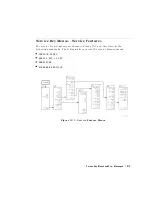
Страница 225: ...Digital Control Group Block Diagram Figure 6 1 Digital Control Group Block Diagram Digital Control Troubleshooting 6 3 ...
Страница 267: ...Figure 7 18 25 MHz HI OUT Waveform from A14J1 Figure 7 19 60 MHz HI OUT Waveform from A14J1 Source Troubleshooting 7 27 ...
Страница 271: ...Figure 7 21 A14 Generated Digital Control Signals Source Troubleshooting 7 31 ...
Страница 301: ...Figure 9 2 Typical Smith Chart Traces of Good Short a and Open b Accessories Troubleshooting 9 7 ...
Страница 302: ......
Страница 366: ......
Страница 378: ...Figure 11 4 Typical ED Re ection Test Port 11 12 Error Terms ...
Страница 380: ...Figure 11 5 Typical ES Re ection Test Port 11 14 Error Terms ...
Страница 382: ...Figure 11 6 Typical ER Re ection Test Port 11 16 Error Terms ...
Страница 384: ...Figure 11 7 Typical EX with 10 Hz Bandwidth Figure 11 8 Typical EX with 3 kHz Bandwidth 11 18 Error Terms ...
Страница 386: ...Figure 11 9 Typical ET 11 20 Error Terms ...
Страница 407: ...Figure 12 5 High Band Operation of the Source Theory of Operation 12 21 ...
Страница 410: ...Figure 12 6 Receiver Functional Group standard and Option 003 12 24 Theory of Operation ...
Страница 411: ...Figure 12 7 Receiver Functional Group Option 003 and 004 Theory of Operation 12 25 ...
Страница 412: ...Figure 12 8 Receiver Functional Group Option 006 12 26 Theory of Operation ...
Страница 413: ...Figure 12 9 Receiver Functional Group Option 004 and 006 Theory of Operation 12 27 ...
Страница 416: ......
Страница 419: ...Figure 13 1 Module Exchange Procedure Replaceable Parts 13 3 ...
Страница 423: ...Major Assemblies Replaceable Parts 13 7 ...
Страница 425: ...Front Panel Assemblies Replaceable Parts 13 9 ...
Страница 427: ...Rear Panel Assemblies Replaceable Parts 13 11 ...
Страница 429: ...Cables Top View Replaceable Parts 13 13 ...
Страница 431: ...Front Panel Cables and Attaching Hardware Replaceable Parts 13 15 ...
Страница 433: ...Rear Panel Cables and Attaching Hardware Replaceable Parts 13 17 ...
Страница 435: ...Source and Sampler Parts Standard and Option 003 Replaceable Parts 13 19 ...
Страница 437: ...Source and Sampler Parts Option 004 006 Replaceable Parts 13 21 ...
Страница 439: ...Source and Sampler Parts Options 004 and 003 004 Replaceable Parts 13 23 ...
Страница 441: ...Source and Sampler Parts Option 006 Replaceable Parts 13 25 ...
Страница 443: ...Display Bezel Assembly Replaceable Parts 13 27 ...
Страница 445: ...Chassis Parts Replaceable Parts 13 29 ...
Страница 447: ...Top View of Attaching Hardware and Post Regulator Fuses Replaceable Parts 13 31 ...
Страница 449: ...Bottom View of Attaching Hardware Replaceable Parts 13 33 ...
Страница 488: ......