background image

3 - CONTROLS AND INSTRUMENTS

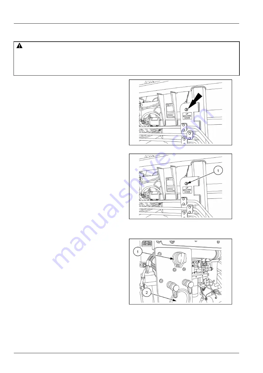
Outside cab end up — down switch

DANGER

Crushing hazard!
Keep away from the lift jack pad when you lower the jack. Make sure that your body is clear of the
area underneath the lift jack pad.
Failure to comply will result in death or serious injury.

D0197A

Machine Up or Down: This control is used to lift or lower
the cab end of the bagger by lowering or raising the lift
jack at the cab end. It is located on the frame next to the
inoculant tank.

RAIL16GEN0078AA

9

Use this control

(1)

to lift the cab end of the bagger. Lift

the bagger up only as far as needed to rotate the wheels
or to hitch to a tow vehicle. This switch is spring loaded
and will return to the center (Off) position when released.
Push the switch up to lower the lift jack (raise machine).
Push the switch down to raise the lift jack (lower machine).

Be sure to raise the lift jack completely before moving the
bagger and during bagging operation.

RAIL16GEN0078AA

10

Battery disconnect switch

The battery disconnect switch

(1)

is located above the

signal lights

(2)

on the engine frame. Be sure the switch

is in the “ON” position before attempting to operate the
bagger. The switch can remain in the “ON” position unless
there is a power drain on the batteries, then turn the switch
to the “OFF” position when the bagger is not being used,
this will disconnect the batteries from the bagger electrical
system.

RAIL16GEN0079AA

11

3-36

Содержание LX1214

Страница 1: ...Part number 47994384 1st edition English November 2016 OPERATOR S MANUAL LX1214 Self Propelled Silage Bagger ORIGINAL INSTRUCTIONS ...

Страница 2: ...es 2 2 Emergency exit 2 9 California proposition 65 warning 2 10 Ecology and the environment 2 11 Safety signs 2 12 3 CONTROLS AND INSTRUMENTS Access to operator s platform Access to operator s platform 3 1 Operator s seat Operator s seat 3 3 Operator seat Control identification 3 3 Instructional seat Instructor s seat 3 3 Forward controls Direction and steering joystick 3 4 Floor controls Brake p...

Страница 3: ...OPERATING INSTRUCTIONS Commissioning the unit Before starting the engine 4 1 Starting the unit Normal engine starting 4 1 Stopping the unit Stopping the engine 4 3 Stopping the unit 4 4 Moving the unit Moving the unit 4 5 Parking the unit Parking the machine 4 8 5 TRANSPORT OPERATIONS Road transport Transporting on a trailer 5 1 Transporting with a tow vehicle 5 3 Preparing for road transport Prep...

Страница 4: ...ice 7 2 Tire and rim service 7 3 Hydraulic system 7 5 Air system overview 7 8 Filters and belts 7 9 Windshield washer reservoir 7 10 Recommended lubricants and coolants 7 11 Filling the fuel tank 7 12 Engine coolant system 7 14 Organic Acid Technology OAT coolant 7 16 General battery maintenance 7 18 Battery jump starting posts 7 20 Fuse and relay locations 7 21 Maintenance planning Maintenance ch...

Страница 5: ...ve chain 7 49 Engine air filter Replace 7 50 Clean air conditioner condenser 7 52 Clean hydraulic oil cooler 7 53 Cab air filters Replace 7 54 Replace engine coolant conditioner filter 7 55 Replace engine coolant filter 7 56 Weekly maintenance 50 hours Lubricate steering tie rods 7 57 Lubricate bag boom 7 58 Lubricate wheel column posts 7 59 Lubricate brake pivot arms 7 60 Lubricate lift slide tub...

Страница 6: ...87 Clean engine vent tube 7 88 Grease feed table wheel bearings 7 89 Check winch oil level 7 90 Replace engine coolant filter 7 91 Every 750 hours Check the air intake system 7 92 Check engine speeds 7 93 Every 1000 hours Hydraulic oil Replace 7 94 Every 2 years Engine coolant drain and flush 7 95 Replace engine coolant thermostat 7 97 Every 1500 hours Check fuel injector nozzles 7 98 Engine serpe...

Страница 7: ...8 TROUBLESHOOTING Fault code resolution Engine fault codes 8 1 Symptom s Machine functions troubleshooting 8 9 9 SPECIFICATIONS Machine specifications 9 1 ...

Страница 8: ......

Страница 9: ...f the machine Reads and understands the manual s pertaining to the machine Reads and understands all safety decals on the ma chine Clears the area of other persons Learns and practices safe use of machine controls in a safe clear area before operating this machine on a job site It is your responsibility to observe pertinent laws and reg ulations and follow CNH Industrial America LLC instruc tions ...

Страница 10: ...adjusting the machine settings for specific field settings etc Routine service and maintenance are those actions which must be performed daily to maintain proper the machine function by an owner operator who is familiar with the ma chine characteristics and who is complying with the infor mation on routine service and safe practices in this man ual and in the decals on the unit Routine service and...

Страница 11: ...1 GENERAL INFORMATION Your machine RAIL16SP00177FA 1 Ag Bag silage bagger 1 3 ...

Страница 12: ...ice parts Your dealer has technicians with special training that know the best methods of repair and maintenance for your ma chine Make sure the machine is calibrated before being placed in service and at regular intervals thereafter in accordance with procedures outlined in this manual and in the control system manual It is the operator s responsibility to keep the system properly calibrated and ...

Страница 13: ...r other product safety information provided with the ma chine These materials define the machine s intended use Use only approved accessories and attachments de signed for your machine Consult an authorized AG BAG dealer on changes additions or modifications that can be required for this machine to comply with various country regulations and safety requirements Unauthorized modifications will caus...

Страница 14: ...The maximum power of emission equipment radio telephones etc must not exceed the limits imposed by the national authorities of the country where you use the machine The electro magnetic field generated by the add on system should not exceed 24 V m at any time and at any lo cation in the proximity of electronic components The add on equipment must not interfere with the functioning of the on board ...

Страница 15: ...TION Operator s manual storage Keep the operators manual and other related materials inside the storage bag provided with the machine The Operator s manual must be available for use by all oper ators of the machine 1 7 ...

Страница 16: ...e refer to this number and your product model number when requiring service or parts information Record the machine serial number model number date of purchase and dealership name in the space provided below The right hand and left hand sides of the machine are determined from a position standing at the bag tunnel side looking toward the feed table Serial number Model number Date Purchased Dealers...

Страница 17: ... right hand side and the left hand side of the machine are determined from a position standing at the bag tunnel side and looking towards the feed table RAIL16SP00178FA 1 1 Right hand side 2 Left hand side 3 Front Feed table 4 Rear Bag tunnel 1 9 ...

Страница 18: ...1 GENERAL INFORMATION Machine components RAIL16SP00179FA 1 1 Operator s cab 5 Lift jack 2 Bag tunnel 6 Operator s platform 3 Engine compartment 7 Bag lift boom 4 Feed table 1 10 ...

Страница 19: ...eath or serious injury The color associated with WARNING is ORANGE CAUTION indicates a hazardous situation that if not avoided could result in minor or moderate injury The color associated with CAUTION is YELLOW FAILURE TO FOLLOW DANGER WARNING AND CAUTION MESSAGES COULD RESULT IN DEATH OR SERIOUS INJURY Machine safety NOTICE Notice indicates a situation that if not avoided could result in machine...

Страница 20: ...hanging items can become entangled in moving parts Wear protective equipment when appropriate DO NOT attempt to remove material from any part of the machine while it is being operated or while components are in motion Make sure that all guards and shields are in good con dition and properly installed before you operate the ma chine Never operate the machine with shields removed Always close access...

Страница 21: ...e before you connect or disconnect fluid lines Stop the engine and remove the key before you connect or disconnect electrical connections Scalding can result from incorrect removal of coolant caps Cooling systems operate under pressure Hot coolant can spray out if you remove a cap while the sys tem is hot Allow the system to cool before you remove the cap When you remove the cap turn it slowly to ...

Страница 22: ...itions At least once each day remove debris accumulation around moving components such as bearings pulleys belts gears cleaning fans etc More frequent cleaning of your machine may be necessary depending on the operating environment and conditions Inspect the electrical system for loose connections and frayed insulation Repair or replace loose or damaged parts Do not store oily rags or other flamma...

Страница 23: ...o the operator or bystanders When doing stationary PTO work keep clear of all moving parts and make sure that appropriate guards are in place Never use a spline adaptor Match the right tractor PTO spline and speed with the PTO driveshaft provided with an implement This will assure proper geometry and operating speed Never operate 540 RPM implements at 1000 RPM Never operate 1000 RPM implements at ...

Страница 24: ...OULD CAUSE DEATH OR SERIOUS INJURY IN THE EVENT OF FIRE TIP OVER ROLL OVER COLLISION OR ACCIDENT Seat belts are part of your protective system and must be worn at all times The operator must be held to the seat inside the frame in order for the protective system to work Air conditioning system The air conditioning system is under high pressure Do not disconnect any lines The release of high pressu...

Страница 25: ...f you can leave your position without touching lines jump clear of the ma chine to make sure that you do not make contact with the ground and the machine at the same time Do not permit anyone to touch the machine until power has been shut off to the power lines Electrical storm safety Do not operate machine during an electrical storm If you are on the ground during an electrical storm stay away fr...

Страница 26: ...r supported if they are left in a raised position for service or access Loader buckets forks etc or other lifting handling or digging equipment and its load will change the center of gravity of the machine This can cause the machine to tip on slopes or uneven ground Load items can fall off the loader bucket or lifting equip ment and crush the operator Care must be taken when lifting a load Use pro...

Страница 27: ...iewed from operator s seat is also an emergency exit Pull the tab to remove the rubber rope around the window Once the rubber rope is removed the window can be pushed out and allowed to fall free Contact your Ag Bag dealer for a replacement window RAIL16GEN0082AA 1 2 9 ...

Страница 28: ...2 SAFETY INFORMATION California proposition 65 warning BT09A213 1 2 10 ...

Страница 29: ...mplies with all local legislation and available resources Do not allow coolant mixtures to get into the soil Col lect and dispose of coolant mixtures properly Do not open the air conditioning system yourself It contains gases that should not be released into the atmosphere Your AG BAG dealer or air conditioning specialist has a special extractor for this purpose and can recharge the system properl...

Страница 30: ...rsh chemicals may damage or remove safety signs Replace all safety signs that are damaged missing painted over or illegible If a safety sign is on a part that is replaced make sure the safety sign is installed on the new part See your dealer for replacement safety signs Safety signs that display the Read Operator s Manual symbol are intended to direct the operator to the Operator s manual for furt...

Страница 31: ...2 SAFETY INFORMATION Safety signs and decal locations RAIL16SP00180FA 1 RAIL16SP00181FA 2 2 13 ...

Страница 32: ...2 SAFETY INFORMATION RAIL16SP00182FA 3 RAIL16SP00183FA 4 2 14 ...

Страница 33: ... 331096B2 English quantity 3 Shield is off RAIL16SP00160AA 6 WARNING Shield is off Replace shield before operating Failure to heed could result in death or personal injury Location 2 Located next to the engine compartment and on the front and back sides of the belt guard Sign 3 21 09024 English quantity 1 High pressure warning RAIL16SP00161AA 7 WARNING Avoid high pressure fluids Avoid the hazard b...

Страница 34: ...1 Warning shield is off or open RAIL16SP00162AA 9 WARNING Shield is off or open Replace or close shield before operating Failure to heed could result in death or personal injury Location 5 Located on the shield near the cab Sign 6 16 20181 English quantity 2 Warning rotating parts RAIL16SP00163AA 10 WARNING Rotating parts inside Keep your body and clothing away Failure to heed could result in deat...

Страница 35: ...injury If you have questions contact your dealer or Miller St Nazianz at 920 773 2121 Location 7 Located next to the cab door Sign 8 21 09025 English quantity 4 Danger pinch point RAIL16SP00185AA 12 DANGER Pinch hazard exists Keep hands feet and body clear of all moving parts and oscillating points Location 8 Located on the lift jacks and to the left of the bag tunnel Sign 9 21 09026 English quant...

Страница 36: ...ersonal injury Location 10 Located on the guard walls of the feed table Sign 11 42 0900820 English quantity 6 Danger entanglement hazard RAIL16SP00188AA 15 Danger Entanglement hazard Revolving rotor Do not climb on or into hopper during machine operation Disconnect power before servicing Failure to heed will result in death or personal injury Location 11 Located on the guard walls of the feed tabl...

Страница 37: ...heel pivot at the engine end and the cab end of the machine feed table side or tunnel side Wheel pivot engine end feed table side 1 Wheel pivot engine end tunnel side 2 Wheel pivot cab end both wheel pivots 3 Cab platform 4 RAIL16GEN0022AA 16 RAIL16GEN0023AA 17 RAIL16GEN0024AA 18 RAIL16GEN0025AA 19 2 19 ...

Страница 38: ...2 SAFETY INFORMATION Slow Moving Vehicle SMV and red reflec tive decal 907225 Slow Moving Vehicle SMV 1 Located on the rear pulley cover 907219 Red retroreflective decal 2 RAIL16GEN0026AA 20 2 20 ...

Страница 39: ...from the storage position under the platform To unlock the ladder pull the ladder lock 2 out to unlock then pull the ladder from the transport position Pull the ladder out from under the platform and allow the ladder to swing down to the operating position 3 Always use the platform ladder to gain access to the op erators cab Be sure to position and lock the ladder under the platform before transpo...

Страница 40: ...utside door handle 1 is equipped with a key lock This lock uses the same key as the ignition Push the button 2 to open the door from the outside The inside door release 3 is a squeeze release located on the center bar 4 RAIL16GEN0068AA 3 RAIL16GEN0069AA 4 3 2 ...

Страница 41: ...tton quick releases and automatic retraction to allow unrestricted exiting and entering of the seats Be sure to always wear your seat belt when operating this vehicle RAIL16GEN0071AA 2 Operator seat Control identification Seat belt Seat belts are standard equipment on both the operator seat as well as the training seat The lap type seat belts have push button quick releases and automatic retractio...

Страница 42: ...e the joystick 1 in the direction you want to travel forward or reverse Move the joystick side to side to steer The trigger 2 at the front of the joystick must be pressed RAIL16GEN0038AA 2 In transport mode the joystick controls steering on the engine end only The electronic control system will steer the cab end wheels to follow the engine end Steering angles are limited to approximately 20 degree...

Страница 43: ...2 at the front of the joystick engaged pressed and the button 3 on the top of the joystick engaged pressed RAIL16GEN0038AA 5 NOTE Trailer Mode is recommended when loading or un loading machine from a trailer RAIL16GEN0039AA 6 Driving in bag mode 1 Be sure to raise the lift jacks before transporting 2 Release the parking brake 3 Move the joystick 1 in the direction you want to travel Move the joyst...

Страница 44: ...he joystick front to back to steer RAIL16GEN0044AA 8 RAIL16GEN0038AA 9 Switching driving modes The modes can be switched depending on type of driving you are doing This has to be done before operating joy stick The modes are Trailer mode Transport mode Bagging mode Switch from transport to trailer mode Switch to the trailer mode press the F3 key 1 on the display Trailer mode 2 will display RAIL16G...

Страница 45: ...atically steer to match engine end RAIL16GEN0040AA 11 If the F3 key 1 is pressed with the wheels more than 5 degrees apart In Between Mode 2 will be indicated on the display RAIL16GEN0041AA 12 Press the Align switch 1 on the switch panel on the right side corner post steer the wheels to within 5 degrees then press the Drive switch 2 Transport Mode 3 will display RAIL16GEN0042AA 13 RAIL16GEN0040AA ...

Страница 46: ...ugh to slightly lift the wheels 6 Steer the engine end wheels to 90 degrees 2 de grees 7 Lower the engine end wheels to the ground by lifting the jack all the way up 8 Press the Drive 1 switch on the switch panel on the right side corner post Cab end will automatically steer to match the engine end If the wheels are more than 5 degrees apart In Between Mode 2 will be indicated on the display RAIL1...

Страница 47: ...3 CONTROLS AND INSTRUMENTS Mode on the display will switch to Bag Mode 1 RAIL16GEN0044AA 19 3 9 ...

Страница 48: ...operators seat and the windshield The brake pedal is used to apply the wheel brakes when moving the vehicle and also to assist in bagging when starting a new bag Apply the brakes as needed to start a new bag until the anchors have been set and the brake pressure has been properly adjusted RAIL16GEN0036AA 1 3 10 ...

Страница 49: ...ximum air conditioning is needed turn the temper ature control knob 3 to Max Cold and the fan speed control knob to the fastest speed Lower the fan speed to medium as cab cools and then to low if necessary Wait three or four minutes between adjustment for the cab tem perature to stabilize If cab is still too cool turn the temperature control knob toward Max Hot until the air temperature is comfort...

Страница 50: ...er Beater Control Switch Clockwise Off Counterclockwise 2 Signal Light Switch Red Green On Off 3 Signal Light Switch Amber On Off 4 Inoculant Spray Applicator Switch On Off 5 Anchor Float Switch On Off 6 Anchor Switch In Out 7 Engine Throttle Control Switch Increase and Decrease Engine RPM 8 Engine High Idle Switch On Off 9 Tunnel Clean out Switch Open Close 10 Feed Table Lift Lower Switch Up Down...

Страница 51: ...n the green signal lights on Position the switch in the center position 4 to turn both signal lights off Use this switch in conjunction with the amber signal light switch 5 to alert anyone around the bagger as to the op erational status Go over the colors used for each mes sage intended before any operation is started Once op eration is started do not stray from the intended message for each light...

Страница 52: ... the machine Refer to 7 101 for cleaning prior to storage This tank and system should be drained and cleaned daily Refer to 6 50 RAIL16GEN0027AA 5 Anchor float switch The anchor float switch 1 is a two position rocker switch which turns the anchor float on and off When the anchor float is turned on a icon will appear on the display panel on the right side corner post alerting the operator that the...

Страница 53: ...switch which must be held in position When the switch is released it will return to the center off po sition Push and hold the top 2 of the switch in to increase the engine speed Push and hold the bottom 3 of the switch in to decrease the engine speed When the switch is released it will return to the center po sition 4 and will maintain the engine speed it was running at when the switch was releas...

Страница 54: ...ely closed the icon on the dis play will disappear Do not turn the rotor on unless the icon has disappeared RAIL16GEN0032AA 11 RAIL16GEN0033AA 12 Feed table lift lower switch The feed table lift lower switch 1 is a three position mo mentary switch which must be held in position When the switch is released it will return to the center off position 2 Push and hold the top 3 of the switch in to lift ...

Страница 55: ...ine end of the machine any higher than needed to rotate the wheels into position RAIL16GEN0032AA 15 Cab end lift jack switch DANGER Crushing hazard Keep away from the lift jack pad when you lower the jack Make sure that your body is clear of the area underneath the lift jack pad Failure to comply will result in death or serious injury D0197A The cab end lift jack switch 1 is a three position mo me...

Страница 56: ...e RAIL16GEN0037AA 18 Feed table belt control The feed table belt control 1 is located at the front of the right side console Move the feed table joystick to the left 2 to have the feed table belt start to move toward the rotor Pushing the joystick further to the left will increase the speed of the belt The joystick is friction controlled and will maintain any setting Move the joystick back to the ...

Страница 57: ...3 CONTROLS AND INSTRUMENTS Cup holder The cup holder in front of the right side console is large enough to accommodate large beverage cans or cups RAIL16GEN0057AA 20 3 19 ...

Страница 58: ...ors seat and in front of the right side armrest The joystick has two additional controls on it for use with other modes A trigger 2 is located on the front side of the joystick handle and a push button 3 is located on the top of the joystick handle Refer to 3 4 for an explanation of what the joystick will control RAIL16GEN0038AA 1 3 20 ...

Страница 59: ... apply push to release control It is located on the right side corner post of the cab above the system pressure gauge 2 and the ignition switch 3 Pull the yellow control knob 1 out to apply the parking brake The parking brake is set with the absence of air pressure Push the yellow control knob 1 in to release the parking brake The parking brake requires air pressure to release Always apply the par...

Страница 60: ...o wheel drive 2 In this position only the engine end wheels will drive Two wheel drive is used in the transport drive mode only and allows the bagger to travel at a higher ground speed than four wheel drive When in two wheel drive ONLY drive on smooth level surfaces and Do Not make sharp turns Push the bottom of the switch in for four wheel drive 3 In this position all four wheels will be driving ...

Страница 61: ... the rotor drive clutch and is located on the right side corner post of the cab This controller also monitors all functions of the clutch Refer to the HPTO clutch controller installation mainte nance manual supplied with your bagger for all informa tion regarding the functions indicated and LED indicators on the face of the controller RAIL16GEN0053AA 9 3 23 ...

Страница 62: ...e bottom of this page for each LED location RAIL16GEN0258FA 10 Item Description 1 Power 2 Input speed detected 3 Output speed detected 4 Pressure transducer detected 5 SAE J1939 can detected 6 Clutch engaged 7 Oil pressure 8 Oil temperature 9 Filter clogged 10 Safety switch 11 Timed lockout 12 Clutch overload 13 Rpm too high 14 Coil fault 3 24 ...

Страница 63: ...3 CONTROLS AND INSTRUMENTS Armrest storage box The right hand armrest has a lift up cover to access the storage compartment RAIL16GEN0058AA 1 3 25 ...

Страница 64: ...n 1 The ignition switch must be in the run position for the wind shield wiper to work To activate the windshield washer press and hold the top 2 of the wiper switch 3 in The washer will be activated as long as the switch is held in position When the switch is released it will return to the wiper position 4 RAIL16GEN0055AA 2 Windshield washer reservoir Keep the windshield washer reservoir full with...

Страница 65: ...he cab Hazard switch 1 Push the top 2 of the switch in to turn the lights on Push the bottom 3 of the switch in to turn the lights off This switch controls the three lights 4 around the bottom of the cab as well as the light 4 mounted under the engine air cleaner 5 RAIL16GEN0059AA 4 RAIL16GEN0062AA 5 RAIL16GEN0063AA 6 RAIL16GEN0064AA 7 3 27 ...

Страница 66: ...controls the outer 4 and inner 5 lights at the top front of the cab 6 RAIL16GEN0059AA 8 RAIL16GEN0060AA 9 Field switch 1 Push the top 2 of the switch in to turn the lights on This switch controls the middle light 3 in each set of lights at the top front of the cab 4 Push the bottom 5 of the switch in to turn the lights off RAIL16GEN0059AA 10 RAIL16GEN0060AA 11 3 28 ...

Страница 67: ...middle 2 position to turn the feed table 3 work lights on Push the top 4 of the switch in to turn the boom work light 5 on along with the feed table 3 work lights Push the bottom 6 of the switch in to turn all the feed table and boom work lights off RAIL16GEN0059AA 12 RAIL16GEN0061AA 13 RAIL16GEN0147AA 14 3 29 ...

Страница 68: ...sition If maximum air conditioning is needed turn the temper ature control knob 3 to Max Cold and the fan speed control knob to the fastest speed Lower the fan speed to medium as cab cools and then to low if necessary Wait three or four minutes between adjustment for the cab tem perature to stabilize If cab is still too cool turn the temperature control knob toward Max Hot until the air temperatur...

Страница 69: ...ating counterclockwise will decrease the minutes 6 Press the dspl time button 1 again to complete the time set procedure The display will return to the de fault display 7 At any time during the time set process not pressing a button or rotating the knob for 5 seconds will cancel the time set mode return the radio to normal opera tion and keep whatever changes you have made For setting all other fu...

Страница 70: ...u have a radio with a cd player this radio can not be reprogrammed for frequencies outside of North America RAIL16GEN0048AA 3 Two way radio coax cable The cab is equipped with a two way radio coax cable The radio end of the coax cable 1 is located in the lower right rear corner of the cab near the fuse block 2 Remove the plastic tie wrap and pull the required amount of cable out of the corner of t...

Страница 71: ...reach out farther from the tunnel to position the bag on the tunnel Be sure the boom winch is out far enough to allow extension of the boom If cable is not out far enough winch damage can result Boom Winch Up or Down 4 Use this control to lower the winch cable down to pick up the bag with the bag cradle and raise up into position Use also to lift and lower the tunnel extension into position NOTE T...

Страница 72: ...eration RAIL16GEN0073AA 3 Outside controls remote control The bag boom and bag pan can be controlled by remote control giving the operator greater flexibility and move ment NOTE When the remote control is activated the wheel drive controls inside the cab are locked out To operate with the remote control the remote must be at tached to the remote control connection point 1 located on the panel with...

Страница 73: ...tch To operated the bag pan 3 boom rotate 4 and extend 5 switches move the switches side to side The winch 1 and boom 2 switches allow variable speed operation of these functions RAIL16GEN0075AA 6 To quickly disengage power to the hand held remote switches press down on the emergency stop button 1 Lift the button to re engage power to the control RAIL16GEN0075AA 7 When the remote 1 is attached to ...

Страница 74: ...ls or to hitch to a tow vehicle This switch is spring loaded and will return to the center Off position when released Push the switch up to lower the lift jack raise machine Push the switch down to raise the lift jack lower machine Be sure to raise the lift jack completely before moving the bagger and during bagging operation RAIL16GEN0078AA 10 Battery disconnect switch The battery disconnect swit...

Страница 75: ...monitor The display monitor can monitor functions of the bagger as well as provide a means to adjust certain features Display monitor buttons The following table identifies the buttons on the display Some of the controls bring up additional features follow the instructions on the screen when prompted 1 F1 key 2 F2 key 3 F3 key 4 F4 key 5 Back arrow 6 Menu button 7 Down adjustment arrow 8 Setting O...

Страница 76: ...tem monitor display to bring up the main menu 2 Press the F1 key 2 at the bottom of the display to get to the Adjust screen 3 RAIL16GEN0196AA 2 RAIL16GEN0197AA 3 3 Use the up 1 or down 2 arrows on the right side of the display to highlight Engine Adjust Group and press OK 3 RAIL16GEN0197AA 4 4 Use the up 1 or down 2 arrows on the right side of the display to highlight Hi Speed Idle and press OK 3 ...

Страница 77: ...m of the display 6 Press the F1 key 2 or use the Back arrow key 3 next to the menu key to return to the main menu RAIL16GEN0199AA 7 Setting reversing fan parameters The reversing fan time and interval between reversings can be reset Fan Reverse Time Duration Reset as follows 1 Press the menu button 1 at the lower right corner of the System monitor display to bring up the main menu 2 Press the F1 k...

Страница 78: ...e and press OK 3 RAIL16GEN0201AA 11 5 Use the up 1 or down 2 arrows on the right side of the display to change the value 3 fan reverse time When desired duration is reached press the OK 4 button to set RAIL16GEN0202AA 12 NOTE If anytime you want to return to the factory default settings press the F2 key 1 at the bottom of the display 6 Press the F1 key 2 or use the Back arrow key 3 next to the men...

Страница 79: ...the F1 key 2 at the bottom of the display to get to the Adjust screen 3 RAIL16GEN0196AA 14 RAIL16GEN0203AA 15 3 Use the up 1 or down 2 arrows on the right side of the display to highlight Fan Reverse Parameters and press OK 3 RAIL16GEN0203AA 16 4 Use the up 1 or down 2 arrows on the right side of the display to highlight Fan Reverse Interval and press OK 3 RAIL16GEN0204AA 17 3 41 ...

Страница 80: ...the Back arrow key 3 next to the menu key to return to the main menu RAIL16GEN0205AA 19 Resetting steering sensors If the steering angles on the System Monitor display do not match the actual steering angles on the bagger the steering sensors need to be reset Reset as follows 1 Place the steering in the Alignment mode Press the Alignment switch 1 2 Steer the wheels on the bagger so they are in lin...

Страница 81: ...eering sensors RAIL16GEN0207AA 22 5 Once the F1 key 1 is pressed the Confirmation window will display Press the Continue F2 key 2 to zero Home the sensors RAIL16GEN0208AA 23 RAIL16GEN0209AA 24 6 Press the F4 key 1 at the bottom of the display to return to the main menu RAIL16GEN0209AA 25 3 43 ...

Страница 82: ...CONTROLS AND INSTRUMENTS 7 Press the Drive 1 switch RAIL16GEN0042AA 26 Cab features Storage compartment The right hand armrest has a lift up cover to access the storage compartment RAIL16GEN0058AA 1 3 44 ...

Страница 83: ...to diagnose engine related problems from inside the cab The cab connector is located on the side of the right side cab corner post RAIL16GEN0072AA 1 System monitor programming port The system monitor programming port 1 is located below the engine data link connector 2 on the side of the right side corner post in the cab This programming port should only be used by a qualified service technician RA...

Страница 84: ...e power strip are available with either cigarette lighter style adapters or individual key switched or unswitched power wires See your dealer for ordering Available plug can be ordered from your dealer The power strip is located to the right of the operators seat next to the side window RAIL16GEN0080AA 3 RAIL16GEN0081AA 4 Auxiliary power outlet The auxiliary power outlet located on the rear cab wa...

Страница 85: ...il is within 2 min at 1200 RPM In severe cold it may be necessary to continue warm up for an additional 4 min But after 6 min of warm up either the engine or oil is not ready check for other causes When hydraulic oil is operated cold it will create a whining noise This is normal due to oil cavitation The noise will subside as the hydraulic pumps circulate the hydraulic oil and it warms up Reduce s...

Страница 86: ... the hot turbocharger and avoid damaging it Before shutting off the engine allow it to idle for several minutes under 1000 rpm to cool the turbocharger turbine 1 Turn the key to RUN RAIL16GEN0050AA 1 2 Check for error codes on the System Monitor display Press the F2 key 1 on the display to clear RAIL16GEN0169AA 2 3 Check for any bystanders around the bagger RAIL16GEN0126AA 3 4 2 ...

Страница 87: ...Stopping the unit Stopping the engine Before stopping the engine after operating under heavy load run the engine at low idle speed for 3 5 min This allows the engine and turbocharger temperature to de crease gradually Restart the engine immediately if the engine stops when operating under load This will prevent heat build up caused by stoppage of oil flow used for cooling and lubrication Stopping ...

Страница 88: ... operators seat and the windshield The brake pedal is used to apply the wheel brakes when moving the vehicle and also to assist in bagging when starting a new bag Apply the brakes as needed to start a new bag until the anchors have been set and the brake pressure has been properly adjusted RAIL16GEN0036AA 1 4 4 ...

Страница 89: ...ystick for an ex planation of what the joystick will control RAIL16GEN0038AA 1 Driving modes The machine has three driving modes Transport Trailer and Bag The modes can be switched depending on type of driving you are doing This has to be done before operating joystick Switching Driving Modes The driving mode for the machine can be switched from one mode to the next using the display panel mounted...

Страница 90: ...ks before transporting 2 Release the parking brake 3 Move the joystick in the direction you want to travel Move the joystick forward or backward to drive and side to side to steer The trigger at the front of the joystick must be engaged pressed RAIL16GEN0038AA 4 In transport mode the joystick controls steering on the engine end only The electronic control system will steer the cab end wheels to fo...

Страница 91: ...tick engaged pressed Engine end wheels are steered by moving the joystick side to side with the trigger at the front of the joystick engaged pressed and the button 3 on the top of the joystick engaged pressed RAIL16GEN0038AA 7 NOTE Trailer Mode is recommended when loading or un loading machine from a trailer RAIL16GEN0039AA 8 Driving in Bag Mode 1 Raise the lift jacks 2 Release the parking brake 3...

Страница 92: ...11 Parking the unit Parking the machine NOTICE Never apply the parking brake unless the bag ger is at a complete stop Applying the parking brake while the bagger is in motion will create an abrupt stop causing the operator to be jolted forward Use the brake pedal 1 to bring the bagger to a complete stop Place the joystick 2 in the center position On the right side corner post pull the park brake c...

Страница 93: ...4 OPERATING INSTRUCTIONS On the right side corner post pull the park brake control knob 1 out to apply the parking brakes Shut off the engine and remove the key 2 RAIL16GEN0050AA 3 4 9 ...

Страница 94: ...4 OPERATING INSTRUCTIONS 4 10 ...

Страница 95: ...ely tie the vehicle down Use a minimum of a four corner tie down method Be sure to secure tie downs to sturdy solid points on the frame or tie down points never to vulnerable areas such as cylinder rods or sheet metal areas 5 Close the exhaust by taping the exhaust pipe shut with duct tape to keep the turbocharger from spinning with out lubrication 6 Raise the ladder 1 up into the storage position...

Страница 96: ...ide of the radiator should be secured in place before transporting Locate the slotted tabs 1 under the lip of the screen opposite of the hinge Use a bolt and nut tie strap or some other means to hold the screen in the closed position RAIL16GEN0162AA 4 5 2 ...

Страница 97: ...is visible Make sure you use a towing vehicle with adequate weight NOTE This vehicle is NOT designed to be driven on a public road It MUST be transported on an equipment trailer or towed with the towing hitch 1 Be sure the tow vehicle is rated to tow the bagger RAIL16GEN0163AA 1 2 The wheel lock 1 must be engaged on the engine end wheels RAIL16GEN0255AA 2 3 Raise the ladder 1 for the cab and slide...

Страница 98: ...vehicle 2 Lower the bagger down onto the tow vehicle hitch and raise the lift jack all the way up Never transport the bagger with the lift jack down RAIL16GEN0163AA 6 6 Shut the bagger engine off 7 Close the exhaust by taping the exhaust pipe shut with duct tape to keep the turbocharger from spinning with out lubrication 8 Connect the air lines from the tow vehicle to the air connections on the ba...

Страница 99: ...NS 9 Connect the 7 pin electrical cord between the tow ve hicle and the connection 1 on the bagger The plug terminal 2 on the bagger is wired per the ANSI ASAE S279 13 Specifications RAIL16GEN0168AA 8 RAIL16GEN0273AA 9 5 5 ...

Страница 100: ...a time and lower the side panels down on the feed table belt Be sure the front rubber flap remains out from under the side panels RAIL16GEN0124AA 2 3 Latch the panels together to hold them in place while raising the feed table Be sure to secure the latch rod 1 from one side panel to the latch tab 2 on the other panel Rotate the latch handle 3 to lock the side panels together RAIL16GEN0145AA 3 4 On...

Страница 101: ...l extension is stored on top of the tunnel during transport Be sure the bag cradle is in place before placing the tunnel extension on top of the tunnel 1 Use the bag boom 1 to lift the tunnel extension 2 Connect the hook from the bag boom cable to the lifting eye 3 on the top of the tunnel Remove the slack in the cable RAIL16GEN0119AA 6 2 Remove the retainer pins holding the extension pins 1 to th...

Страница 102: ...lower pins 3 with the hooks 4 on the sides of the tunnel Secure top in place with the retainer pin and clip 5 RAIL16GEN0120AA 9 RAIL16GEN0151AA 10 5 Lower the boom arm 1 down to the top of the tunnel extension 2 and remove the slack in the cable The boom must remain in this position for transport RAIL16GEN0152AA 11 5 8 ...

Страница 103: ...Remove the clip pin 4 holding the cable guide 5 to the welded pin 6 on the frame 4 Swing the cable guides up and pin in the up position with the transport pin and clip 7 RAIL16GEN0251BA 12 RAIL16GEN0028AA 13 Place wheels into transport position 1 Lower the cab end lift jack enough to slightly lift the wheels 2 Press the align switch 1 on the switch panel on the right side corner post 3 Steer the w...

Страница 104: ...he drive switch 3 on the right side corner post 10 Cab end will automatically adjust to match engine end 11 If the drive switch is pressed with the wheels more than 5 apart In Between Mode 4 will be indicated on the display 12 Press the align switch 5 on the switch panel on the right side corner post steer the wheels to within 5 then press the drive switch Transport or trailer Mode 6 will display ...

Страница 105: ...hen not using the transport lock remove the pin 2 and clip 3 raise the lock up 6 away from the wheel column and re insert the pin in the upper hole under the lock to hold it up Clip in place RAIL16GEN0164AA 18 RAIL16GEN0256AA 19 Pintle hitch For transporting with a tow vehicle the tow hitch and hitch brace have to be secured to the cab end of the bagger This hitch is only required when transportin...

Страница 106: ...at the cab end of the bagger RAIL16GEN0116AA 22 5 Using the same pins and clips place the brace 1 between the bagger frame 2 and the pintle end 3 of the hitch Secure in place by placing the pin through the mounting plates 4 and the ends of the brace Clip the pins in place RAIL16GEN0158AA 23 5 12 ...

Страница 107: ...f 12 ft Bag 12 ft 1814 2041 17 kg 2 2 25 ton per 0 3 m 1 0 ft approx Suggested Feed Out Rates Per Day Winter Feed Out Rate October to April Feet per day 0 8 m 2 5 ft Tons per day 4536 5080 2 kg 5 5 6 ton Summer Feed Out Rate May to September Feet per day 1 m 3 ft Tons per day 5443 6123 50 kg 6 6 75 ton Capacity of Tons Per Running Foot of 14 ft Bag 14 ft 2494 76 2721 55 kg 2 75 3 00 ton per 0 3 m ...

Страница 108: ...of site is important Concrete asphalt gravel or packed limestone works well under bags Pick a site away from rodents Protect your site from livestock with fencing Bag installation Enclosed in each box of bags is an instruction sheet with pictures to help you properly install the bag on your bagger Please take time to understand the best method of bag installation The bag should be placed on the ma...

Страница 109: ...otecting the Bag From Wind Damage Wind damage can be caused by the wind whipping the loose end of the bag To prevent damage the loose bag end needs to be secured by placing tires or other soft material on the end of the bag Wind damage can cause small cracks and eventually wear a hole that allows air to penetrate causing feed damage A tightly secured bag will add to the life of the bag Bag Managem...

Страница 110: ...The 14 ft tunnel weighs approximately 2354 kg 5190 lb use a hoist and lifting straps that have the lifting capacity required 12 ft tunnel components RAIL16GEN0271FA 1 Item Description 1 Cab end tunnel support with plates 2 Tunnel mount left side 3 Threaded mount plate tunnel bottom 4 Bracket threaded mount plate tunnel bottom 5 Engine end tunnel support with plates 6 Tunnel mount right side 7 Moun...

Страница 111: ... 5 8 11 x 1 1 2 hex head bolts and the 5 8 11 x 2 socket head screws to the cab end and engine end frame mounting plates Secure in place with 5 8 11 nylon lock flange nuts The outer mounting holes from the 14 ft tunnel to the frame will not be used for the 12 ft tunnel 11 Assemble the tunnel support weldment plates between the left and right tunnel mounts and the corresponding holes in the frame o...

Страница 112: ...EN0093AA 4 14 Place the anchor cables 1 around the cable pulleys 2 under the tunnel and insert the retainer pin 3 next to the pulley RAIL16GEN0091AA 5 15 After the tunnel is in place on the frame insert the nine button head bolts 1 that is used to secure the tunnel floor 2 to the frame Insert the bolts from the top down and secure in place with the nuts on the underside RAIL16GEN0092AA 6 6 6 ...

Страница 113: ... valve plate mounted to the cab side of the tunnel Tighten securely RAIL16GEN0101AA 9 19 Assemble the engine end hand rail 1 to the corner of the hydraulic oil tank 2 at the engine end Place the hand rail mounting plate against the hydraulic oil tank line up the three mounting holes and insert the 3 8 16 x 1 1 4 stainless steel bolts with 3 8 stainless steel flat washers 3 through the hand rail pl...

Страница 114: ...ts Position to fill as much of the gap as possible and tighten securely RAIL16GEN0111AA 11 21 When the tunnel is completely assembled to the bag ger remove the overhead hoist 1 from the top of the tunnel Be sure to fold the lifting loop 2 down against the tunnel to prevent damage to the bag RAIL16GEN0111AA 12 12 ft tunnel removal When removing the tunnel from the bagger be sure to have a level are...

Страница 115: ...e crane to any other points on the tunnel RAIL16GEN0111AA 14 4 Remove the cab end hand rail 1 from the hand rail 2 at the cab end of the bagger Save all items for reassembly RAIL16GEN0111AA 15 5 Remove the engine end hand rail 1 from the corner of the hydraulic oil tank 2 at the engine end Save all items for reassembly RAIL16GEN0110AA 16 6 Remove the anchors from the anchor cable 1 by re moving th...

Страница 116: ...or cables 1 through the pulleys 2 under the tunnel floor Remove the cable retainer pin 3 next to the pulley Save the pin for reassembly RAIL16GEN0091AA 19 9 Remove the 9 button head bolts 1 located behind the clean out plate securing the tunnel floor 2 to the frame Save the button head bolts and nuts for reassembly RAIL16GEN0092AA 20 6 10 ...

Страница 117: ...are for reassembly RAIL16GEN0093AA 21 RAIL16GEN0091AA 22 11 Remove the guard 1 from the planetary end of the rotor on the feed table side This is to access the three allen flat head bolts 2 inline with the rotor that hold the tunnel to the frame Remove all three bolts Save all hardware for reassembly Early production had flat head bolts current production has hex head bolts RAIL16GEN0095AA 23 RAIL...

Страница 118: ...ly Early production had flat head bolts current production has hex head bolts RAIL16GEN0097AA 25 RAIL16GEN0096AA 26 13 Identify and remove the two quick disconnect hoses from the A 1 B 2 ports on the valve block 3 mounted to the tunnel on the feed table side just in front of the cab The valve and hoses from the C D ports remain with the tunnel Valve block shown is on a 12 foot tunnel valve hoses a...

Страница 119: ... the frame Remove the hardware holding the engine end tunnel support 3 to the frame The tunnel supports can remain assembled to the tunnel Save all items for reassembly RAIL16GEN0271FA 28 16 Use the overhead crane to slowly lift and remove the tunnel with clean out door and hydraulic cylinders from the frame Set the tunnel down on wood blocks making sure the tunnel is stable RAIL16GEN0111AA 29 6 1...

Страница 120: ...he overhead crane 1 to the flip up loop 2 on the top of the tunnel Do not attach the overhead crane to any other point on the tunnel RAIL16GEN0088AA 31 2 Use the overhead crane to slowly lift and position the tunnel 1 with clean out door and hydraulic cylinders on to the frame 2 Leave the overhead crane at tached to the tunnel until it is fully assembled to the frame RAIL16GEN0104AA 32 6 14 ...

Страница 121: ...n securely Tighten the four bolts 4 on the other end of the support plate RAIL16GEN0102AA 34 5 Identify and assemble the two quick disconnect hoses from the A 1 B 2 ports on the valve block 3 mounted to the tunnel on the feed table side just in front of the cab The valve and hoses from the C D ports had remained with the tunnel Valve block shown is on a 12 ft tunnel valve hoses are the same as a 1...

Страница 122: ...produc tion or hex head bolts current production saved from removal at the driven end of the rotor on the feed table side These bolts hold the tunnel to the frame and are in line with the rotor Tighten securely RAIL16GEN0096AA 38 9 Assemble the guard over the chains at the driven end of the rotor Secure in place with the hardware saved from removal Tighten securely RAIL16GEN0097AA 39 10 Assemble t...

Страница 123: ...tunnel during removal These bolts hold the tunnel to the frame Four are on the cab end 1 of the tunnel and three are on the engine end 2 of the tunnel Tighten all seven bolts securely RAIL16GEN0093AA 42 RAIL16GEN0091AA 43 13 Behind the clean out plate locate the nine holes 1 in the tunnel floor 2 Line up the holes and insert the nine button head bolts 3 saved from removal through the floor and the...

Страница 124: ...and se curing the cable to the anchor with the two piece ca ble retainers 3 Place a retainer on top side of the anchor and secure in place with the saved hardware Tighten securely Pull the cable down through the anchor and assemble the second two piece retainer tight against the anchor Secure in place with hard ware saved RAIL16GEN0089AA 47 16 Remove the overhead crane from the flip up loop at the...

Страница 125: ...ve all items for reassembly 1 Securely attach the overhead crane 1 to the flip up loop 2 on the top of the tunnel Do not attach the overhead crane to any other point on the tunnel Put a slight tension on the overhead crane but not to the point that the tunnel starts to lift RAIL16GEN0088AA 50 2 Remove the anchors 1 from the anchor cable 2 by removing the two piece cable retainers 3 on each side of...

Страница 126: ...Pull the two anchor cables 1 through the pulleys 2 under the tunnel floor Remove the cable retainer pin 3 next to the pulley Save the pin for reassembly RAIL16GEN0091AA 53 5 Remove the 9 button head bolts 1 located behind the clean out plate securing the tunnel floor 2 to the frame Save the button head bolts and nuts for reassembly RAIL16GEN0092AA 54 6 20 ...

Страница 127: ... for reassembly RAIL16GEN0093AA 55 RAIL16GEN0091AA 56 7 Remove the guard 1 from the planetary end of the rotor on the feed table side This is to access the three allen flat head bolts 2 in line with the rotor that hold the tunnel to the frame Remove all three bolts Save all hardware for reassembly Early production had flat head bolts 2 current production has hex head bolts 3 RAIL16GEN0095AA 57 RAI...

Страница 128: ... had flat head bolts 2 current production has hex head bolts 3 RAIL16GEN0097AA 59 RAIL16GEN0096AA 60 9 Remove the nine bolts 1 from each side of the tunnel between the tunnel support pipes 2 The bottom four on each side have spacers to the inside Save all hardware for reassembly Lower four bolts shown RAIL16GEN0099AA 61 10 Remove the wire harness 1 from the limit switch 2 located on the tunnel sid...

Страница 129: ... the plate and remove the four bolts 3 from the other end of the plate Save all hardware for reassembly The plate can remain attached to the tunnel 4 RAIL16GEN0102AA 64 13 Locate the plate 1 on the engine side of the upper tunnel that holds the tunnel to the frame Loosen the five bolts 2 from one end of the plate and remove the four bolts 3 from the other end of the plate Save all hardware for rea...

Страница 130: ...6 WORKING OPERATIONS 15 Remove the overhead crane from the lifting loop on the tunnel Be sure to fold the lifting loop down RAIL16GEN0088AA 67 6 24 ...

Страница 131: ...ging operation is started 1 The pintle hitch brace 4 should be removed from be tween the tow hitch and bagger frame and stored on the two storage tabs 5 one by each cab end wheel Use the existing pins 6 to secure in place RAIL16GEN0115AA 1 RAIL16GEN0116AA 2 2 Drive the bagger to the spot where the bag is to begin 3 Position the bagger with the tunnel toward the bag starting point Position the bagg...

Страница 132: ...panel on the right side corner post Cab end wheels will steer automatically to match the engine end If the wheels are more than 5 degrees apart In Between Mode 3 will be indicated on the display 13 Press the Align switch 1 on the switch panel on the right side corner post steer the wheels to within 5 degrees then press the Drive switch Cab end wheels will steer automatically to match the engine en...

Страница 133: ...is the top center pin 2 on the extension RAIL16GEN0120AA 2 3 Using the bag boom swing the tunnel extension out and lower to a position in front of the tunnel Line up the five pins 1 on the extension 2 with the five re ceiver tubes 3 on the tunnel Slide the tunnel exten sion pins into the receiver tubes 4 Secure in place with the pins and clips supplied with your bagger RAIL16GEN0121AA 3 5 Unhook t...

Страница 134: ... 1 Pull the lock handle 2 out and rotate into the unlocked position To lock the feed table in the upright position the lock handle must be rotated out of the groove 3 to allow the spring to keep the lock engaged RAIL16GEN0122AA 1 2 Using the feed table raise lower switch 1 on the right side console in the cab lower the feed table 2 to the ground Release the switch when the feed table reaches the g...

Страница 135: ...and rotated to remain in the unlocked up position which is helpful when lowering the side panels down to the feed table RAIL16GEN0123AA 4 RAIL16GEN0124AA 5 4 Stretch the bungee cords 1 from the front panel 2 around the front of each side panel 3 and hook in place 4 to hold the front rubber flap 5 up RAIL16GEN0125AA 6 RAIL16GEN0126AA 7 6 29 ...

Страница 136: ...d 2 On the cab side of the feed table locate the hydraulic drive motor 1 for the feed table belt 3 Loosen the four nuts 2 holding the drive motor mounting plate 3 to the side of the feed table RAIL16GEN0188AA 1 4 Loosen the inner adjustment nut 1 and the outer lock nut 2 on the adjuster rod 3 Use the outer adjust ment nut t 4 o tighten the drive chain 5 After drive chain is tight all slack removed...

Страница 137: ...this may result in belt damage and premature wear of roller bearings Adjust feed table belt as follows 1 Lower the feed table down to the ground 2 Loosen the adjustment bolt lock nut 1 Tighten the adjustment bolt 2 to push the belt away from the side you are tightening Tighten the locknut when finished 3 Adjust the opposite side the same amount 4 Adjust the belt to run straight in the feed table I...

Страница 138: ...le bag ging 2 Remove the clips 3 from the welded pin 4 and lower the guides down Secure in the lowered position with the clips 3 3 Remove the anchors 5 from the hooks 6 and posi tion in front of the tunnel RAIL16GEN0251BA 1 4 Return to the cab sound the horn start the engine and use the anchor in out switch 1 on the right side console to retract both anchors 2 Retract both of them all the way in t...

Страница 139: ... Fully extend the anchor cylinder then retract 25 mm 1 in Shut off the engine when measuring 3 Insert the cable from the outside Use the other cable as a guide when installing the new cable The longer cable 1 is on the engine end and the shorter cable 2 is on the cab end 4 Insert the cable through the cable guide and over the roller 3 RAIL16GEN0274AA 4 RAIL16GEN0246AA 5 5 Guide the cable end 1 aro...

Страница 140: ...e halves 3 flush 10 Tap the sleeve down on to the knob core halves with a hammer 11 Manually pull the cable tight from the outside 12 Mark the cable as close to the fair lead as possible outer edge of pivot assembly 13 Extend the cable 122 cm 48 in Pull the cable while extending 14 Cut the cable at the mark 15 Slide the cable through the center of the anchor In stall the cable stop on to the cable...

Страница 141: ...e removed from the cable 2 Fully extend the anchor cylinder then retract 25 mm 1 in Shut off the engine when measuring 3 Manually pull the cable tight from the outside 4 Mark the cable as close to the fair lead as possible outer edge of pivot assembly 5 Extend the cable 122 cm 48 in Pull the cable while extending 6 Cut the cable at the mark 7 Slide the cable through the center of the anchor Instal...

Страница 142: ...losed and tunnel clean out icon 3 turns off before bagging RAIL16GEN0028AA 1 RAIL16GEN0129AA 2 RAIL16GEN0130AA 3 Bag identification Remember to use only Ag Bag bags They are de signed to fit and function properly Locate the bag size 1 indicated on the box Make sure you are using the correct size for your bagger Locate the arrow 2 on the side of the box It should be pointing toward the bagger RAIL1...

Страница 143: ...sened 3 Loosen the two mounting bolts 2 on each bag pan slide and using the jack slide the bag pan slides up or down Sliding the bag pan slides up will increase the gap Sliding the bag pan slides down will decrease the gap 4 After proper gap is reached tighten both mounting bolts on each bag pan slide mount tube RAIL16GEN0194AA 5 Install The Bag On To The Tunnel 1 Hook the bag boom cable hook to t...

Страница 144: ...e tunnel Carefully work the bag around the tunnel making sure the bag maintains its flat look and is flat between the tunnel and the bag pan 7 Lower the cradle until it is resting on top of the tunnel Make sure the cradle is on the tunnel and not on the tunnel extension The cradle should rest between the two pipes on the top of the tunnel Once the cradle is in place on the tunnel remove all the ti...

Страница 145: ...ster Seal Follow the instructions that are included with the Master Seal 1 Master seal tool 2 both are available from your Ag Bag dealer Use a double knot tie 3 Find the end of the bag gather the bag to the center Twist the bag tight and tie the bag tight Leave enough bag to fold over and tie a second time 4 giving the bag an air tight seal RAIL16GEN0278AA 11 RAIL16GEN0279AA 12 3 Slide the excess ...

Страница 146: ...d with the bagging process By using the RED YELLOW and GREEN communication lights located at the engine end 1 and the cab end 2 of the bagger Sound the horn before starting engine The communication lights are controlled by the two rocker switches on the right side console in the cab Engine end and cab end red yellow green communica tion lights RAIL16GEN0137AA 1 RAIL16GEN0138AA 2 6 40 ...

Страница 147: ...at the lower left corner of the controller and hold for 3 seconds The controller will not engage if activated with the engine rpm over 1100 rpm 4 After the flashing green clutch engaged LED 2 turns solid increase the engine rpm to 1850 by using the throttle switch 3 or the high idle switch 4 on the right side console Watch the System Monitor display for engine rpm Refer to 3 21 for a detailed expl...

Страница 148: ...the operator will have to restart the rotor and feed table once the operator is seated in the operators seat 5 Start the feed table by moving the controller 1 on the right side console in the desired direction either away from the rotor or toward the rotor Moving the controller farther from center will increase the speed of the feed table RAIL16GEN0045AA 6 6 Start the upper beater in a clockwise o...

Страница 149: ...b side brakes to 1 38 bar 20 00 psi using the brake pres sure switches 1 on the right front cab post Watch the System Monitor display for the brake pressure 2 at each end RAIL16GEN0042AA 8 RAIL16GEN0052AA 9 2 Use the brake pedal 1 to control the movement of the bagger when starting a new bag Apply pressure to the brakes as needed RAIL16GEN0036AA 10 3 Check the anchor float switch 1 on the right si...

Страница 150: ...t outside the cab windshield When the anchors are out 2 m 5 ft in dicator pointing to 5 turn off anchor float and watch anchor pressure 2 on System Monitor If anchor pressure stabilizes below 69 bar 1000 psi actuate anchor float switch again to allow anchors to extend an additional 30 cm 12 in indicator pointing to 6 Turn off anchor float and check anchor pressure Re peat this procedure until anch...

Страница 151: ...e decrease the amount of cable fed out as needed to create a smooth bag More cable fed out will increase the drag pressure on the an chors Watch the System Monitor display to monitor the anchor pressure 1 The pressure should be maintained between 69 bar 1000 psi and 103 bar 1500 psi These pressures will vary depending on the moisture of the product being bagged It is important that you continually...

Страница 152: ...r switch 1 on the right side console Increase the brake pressure on the engine and cab end brakes pressing the top of the pressure switches 2 on the right front corner cab post Watch the System Monitor display for brake pressure 3 at each end When the final load is in the bag there should be approximately 5 folds left on the tunnel NOTE If using the inoculant applicator turn it off at this time RA...

Страница 153: ...unless the tunnel clean out is completely closed RAIL16GEN0042AA 21 RAIL16GEN0052AA 22 3 Drive the bagger away from the end of the bag approx imately 1 2 m 4 0 ft to allow the tunnel clean out to operate properly 4 Push and hold the top of the clean out switch 1 on the right side console to open push away from rotor the tunnel clean out When the tunnel clean out is open an icon 2 will appear on th...

Страница 154: ...he bagger forward until the bag has been pulled from the tunnel 8 After the bagger has been moved away pull the plastic flat and prepare to seal the end of the bag Grab each side of the bag on the end Walk the bag over itself pulling the product together Bring the bag end back forward 9 Seal the end of the bag using either Master Seal strips 1 or the double tie 2 method Refer to 6 1 for addi tiona...

Страница 155: ...you want the vent to be installed about 3 m 10 ft from the end and about 3 4 of the way up the height of the bag press the cutter portion of the tool into the plastic to create a hole Push the tool with the threaded portion of the vent 1 through the hole and pull the cutting tool 2 out leaving the threaded end of the vent sticking out through the bag RAIL16GEN0282AA 30 4 Assemble the valve lid 1 o...

Страница 156: ...y tip highlighted on the chart below The pressure can be adjusted with the control knob 1 lo cated under the inoculant tank Watch the pressure gauge 2 in front of the cab for inoculant pressure setting If changing the spray tips there are four spray tips located in the feed hopper RAIL16GEN0113AA 1 RAIL16GEN0114AA 2 Changing the inoculant system The inoculant system should be drained and flushed w...

Страница 157: ...si 250 0 232 10 2 32 0 580 XR11008 07 17269 145 kPa 21 psi XR110015 07 17735 165 kPa 24 psi 4 0 464 0 116 XRC11002 07 09647 103 kPa 15 psi XRC11002 07 09647 207 kPa 30 psi 6 0 696 0 174 XRC110025 07 08287 131 kPa 19 psi XRC110025 07 08287 234 kPa 34 psi 8 0 928 0 232 XRC11003 07 08288 165 kPa 24 psi XRC11003 07 08288 262 kPa 38 psi 500 0 116 10 1 16 0 290 XRC11004 07 08289 152 kPa 22 psi 4 0 309 0...

Страница 158: ...6 WORKING OPERATIONS 6 52 ...

Страница 159: ...old fluids lubricants and filters in accordance with local regulations Check with your local environmental recycling canter or you local dealer for correct information Plastic and resin parts Avoid using gasoline paraffin paint thinner etc when cleaning plastic e g console instrument cluster monitors and gauges etc Use only water mild soap and a soft cloth when you clean these parts Using gasoline...

Страница 160: ...e scheduled in this section NOTICE While any company can perform necessary maintenance or repairs on your equipment AG BAG strongly recommends that you use only authorized AG BAG dealers and products that meet given specifications Improperly or incorrectly performed maintenance and repair voids the equipment warranty and may affect service intervals 7 2 ...

Страница 161: ...t inflate a tire that has had a complete loss of air If the tire has lost all air pressure have a qualified tire mechanic service the tire To add air to a partly inflated tire use the following proce dure 1 Use an air hose with a remote shutoff valve and a self locking air chuck 2 Stand behind the tread of the tire and make sure all persons are away from the side of the tire before you start to ad...

Страница 162: ...re sizes recommended for the vehicle Tire size Tire brand Air pressure Load capacity per tire Speed Loaded radius 445 65R22 5 Bauer built tire 827 kPa 120 psi 5579 kg 12300 lb 105 km h 65 mph 52 3 cm 20 6 in Wheel lug nut torque Check the wheel lug nut torque Torque the lug nuts to 366 N m 270 lb ft Re torque the wheel lug nuts each time a wheel is reinstalled onto the vehicle Check and re torque ...

Страница 163: ... system hydraulic oil characteristics It is important that a quality oil be used to insure proper longevity of hydraulic components Following is the min imum specifications for hydraulic oil to be used on this bagger ISO Classification HV 68 Viscosity cSt 40 C 104 F 69 0 Viscosity cSt 100 C 212 F 11 0 Viscosity SUS 38 C 100 F 352 Viscosity SUS 99 C 210 F 63 4 Viscosity cPs 20 C 4 F 4940 Viscosity ...

Страница 164: ...with clean lint free towels or clean plastic bags plugs or caps Before installing any replacement hose flush the inside of the hose with clean diesel fuel or unused commercial petroleum cleaning solvent for ten seconds minimum Do not use water water soluble cleaners or compressed air NOTE There are three different systems on the bagger Each system uses a different type of oil Never mix oils in the...

Страница 165: ...e or pipe shows signs of wear or damage replace the component IMMEDIATELY Failure to comply could result in minor or moderate injury C0200A 1 Before operating machine carefully make a visual in spection of all hydraulic cylinders looking for leaks and or other damage 2 If hydraulic cylinder damage is found make all neces sary repairs before operating machine 7 7 ...

Страница 166: ...sure to remove all moisture from the air storage tank daily Locate the lanyard 1 that is attached to the moisture drain 2 on the bottom center of the tank 3 The end of the lanyard 1 is looped around the valve 4 at the rear of the tank Pull on the lanyard to open the valve Hold the valve open until all moisture has been removed from the tank Let go of the lanyard and the valve will close RAIL16GEN0...

Страница 167: ...1370 1 Engine Coolant Conditioner Filter S N 4220003 Before 4220005 thru 4220009 Extended Life 42 0801371 1 Engine Coolant Filter S N 4220004 4220010 After OAT Coolant 42 0802369 1 Cab Air Filter Charcoal 21 00955 1 Recirculation Filter In Cab 21 21623 1 Main Hydraulic Oil Return 21 42585 2 Case Drain 21 21112 1 Clutch 42 1541961 1 Rotor Planetary 42 1540167 1 Hydraulic Oil Reservoir Breather 21 2...

Страница 168: ...right side cab window on the outside of the cab Keep the windshield washer reservoir full with windshield washer fluid only Remove the cap from the windshield washer reservoir Fill the reservoir with windshield washer fluid Replace the cap when finished and tighten securely RAIL16GEN0062AA 1 7 10 ...

Страница 169: ...LLAND AMBRA HYDROSYSTEM 68 Tank capacity Approximately 360 L 95 US gal Clutch hydraulic system Oil type CNH HYPOIDE SSL SYNTHETIC GEAR LUBE 80W 140 Reservoir capacity 76 L 20 US gal Rotor planetary drive Oil type CNH HYPOIDE SSL SYNTHETIC GEAR LUBE 80W 140 Planetary capacity 28 4 L 7 5 US gal Feed table planetary drive Oil type CNH HYPOIDE SSL SYNTHETIC GEAR LUBE 80W 140 Planetary capacity 0 59 L ...

Страница 170: ...l the tank when the engine is running 3 Wipe up spilled fuel immediately Failure to comply could result in death or serious injury W0099A The fuel tank 1 is located under the lift up cover 2 walk way between the feed table beater plate and the tunnel Lift up the cover walkway and locate the fuel cap 3 RAIL16GEN0083AA 1 RAIL16GEN0084AA 2 7 12 ...

Страница 171: ...MAINTENANCE The fuel tank capacity is 530 L 140 US gal Replace fuel cap 1 before operating Wipe up any spilled fuel Lower the cover 2 walkway down before operating RAIL16GEN0084AA 3 RAIL16GEN0083AA 4 7 13 ...

Страница 172: ... tank cap while the system is hot To remove the cap allow the system to cool turn the cap to the first notch and wait for all pressure to release Remove the cap only after all pressure has released Failure to comply could result in death or serious injury W0367A The engine radiator 1 charge air cooler 2 rotor plane tary oil cooler 3 clutch and auxiliary hydraulic oil cooler 4 and the air condition...

Страница 173: ... plumbing RAIL16GEN0216AA 3 Adding coolant to the system The following steps are to be followed when draining and refilling the cooling system 1 Shut off the vehicle engine and allow the system to cool 2 Open the radiator top tank cap slowly to relieve system pressure 3 Remove the radiator top tank cap and fill the radiator top tank with coolant 4 Allow the coolant to fill the system completely an...

Страница 174: ...Change the coolant solution at the recommended change interval When changing from conventional coolant to OAT you should follow the Changing coolant types procedure below to attain the full benefit of the coolant Changing coolant types To change from conventional coolant to OAT coolant 1 Empty the engine cooling system by draining the coolant into a suitable container Use the petcock drain 1 locat...

Страница 175: ...7 MAINTENANCE Definition Organic Acid Technology OAT coolant A coolant that relies on inhibitors such as organic acid salts for corrosion and cavitation protection 47488993 3 7 17 ...

Страница 176: ...batteries are located in a compartment under the engine frame on the feed table side of the bagger Unlatch and slide the battery compartment out to access the batteries RAIL16GEN0286AA 1 Keep your batteries in good operating condition as follows 1 Add distilled water as needed to keep separators under water 2 Keep the batteries with a full charge as shown on a hydrometer 3 Keep the batteries clean...

Страница 177: ...jelly or light grease on terminals to prevent more corrosion Inspect the battery cables for damage Replace any battery cable that has damage When batteries are not in use When the bagger is not in use the batteries will need a charge every six weeks A storage battery not in use will slowly discharge A battery that has discharged can freeze at low ambient temperatures and cause damage to the batter...

Страница 178: ...ht panel on the engine frame Be sure to replace the rubber caps when not using the remote terminals Be sure to hook up the positive red terminal 1 to the positive from the auxiliary source Be sure to hook up the negative black terminal 2 to the negative from the auxiliary source RAIL16GEN0079AA 1 7 20 ...

Страница 179: ...d inside a electrical box 1 on the outer rear corner of the cab Unlatch and open the electrical box to access the fuses and relays A decal 2 is located on the frame below the electrical box which identifies which fuse and relay controls which function RAIL16GEN0259FA 1 7 21 ...

Страница 180: ...eld lights F7 10 A Cab heat thermstat F8 5 A Main joystick md3 F9 15 A Cab end xa2 brk pr reg F10 15 A Engine end xa2 fuel pendnt F11 5 A Can 6 module F12 15 A Armrest switches F13 10 A 12 24 conv hpto F14 15 A Inoculant pump JB04 50 A Fdtbl lamp JB05 50 A Drive lamp JB06 50 A Inoculant JB07 50 A Field lamp JB08 50 A Road lamp JB09 50 A Boom lamp CR1 70 A Acc CR2 70 A A C CR3 70 A Ign 7 22 ...

Страница 181: ...7 42 Engine serpentine belt check x 7 43 As required Remove trash debris from chassis and engine area x 7 41 Lubricate feed table bearings x 7 45 Lubricate beater bar bearings x 7 46 Lubricate rotor bearing x 7 47 Lubricate beater bar chain x 7 48 Lubricate feed table drive chain x 7 49 Replacing engine air filters x 7 50 Clean air conditioner condenser x 7 52 Clean hydraulic oil cooler x 7 53 Cab...

Страница 182: ... 89 Check winch oil level x 7 90 Replace engine coolant filter x 7 56 Every 750 hours Check the air intake system x 7 92 Check engine speeds x 7 93 Every 1000 hours Hydraulic oil Replace x 7 94 Every 2 years Engine coolant drain and flush x 7 95 Replace engine coolant thermostat x 7 97 Every 1500 hours Check fuel injector nozzles x 7 98 Engine serpentine belt tensioner check x 7 99 Every 2500 hour...

Страница 183: ... the belt to slip Do not apply belt dressing to this belt as this will damage the belt and cause premature failure Proper adjustment is when the belt deflection mid way between the upper 1 and lower 2 pulleys at both edges of belt is 6 35 mm 0 25 in of deflection with 31 kg 69 lb of pressure for a belt with more than 10 hours of use For a new belt the deflection should be 6 35 mm 0 25 in with 47 k...

Страница 184: ...uster nuts The wrench is in a storage tube at the front corner of the engine frame on the feed table side RAIL16GEN0193AA 4 2 Loosen the adjuster locknuts 1 on the four corners of the engine frame 3 Turn the top adjuster nut 2 to move the entire en gine frame assembly up Turn all four adjuster nuts the same amount to keep the engine level and in alignment Adjustment usually only requires 1 8 to 1 ...

Страница 185: ...AINTENANCE Tire lug nuts Check the wheel lug nut torque after the first 10 hours of use After a wheel has been installed check the torque after one hour of use Torque the lug nuts to 366 N m 270 lb ft 7 27 ...

Страница 186: ... RAIL16GEN0211AA 2 To check the engine oil level the bagger should be on level ground Check the oil before starting the unit Make sure the dipstick 1 is pushed in completely If the oil level is below the low level on the dipstick add NEW HOLLAND AMBRA MASTERGOLD ENGINE OIL CJ 4 SAE 15W 40 oil through the crankcase fill cap 2 to bring the oil level up to the high level mark Do not raise the level a...

Страница 187: ...16GEN0236AA 1 If oil is low clean the area around the filler breather plug 1 at the top of the planetary This plug can be accessed from either side of the bagger Remove the filler plug and add CNH HYPOIDE SSL SYNTHETIC GEAR LUBE 80W 140 until the level is in the center of the sight gauge Re install the fill plug and tighten securely Recheck oil level with engine running and rotor off If oil level ...

Страница 188: ... MAINTENANCE Check HPTO reservoir oil level Check the oil level in the reservoir If oil is low add MOBIL 424 to bring the oil up to the full mark on the reservoir Do not over fill RAIL16GEN0234AA 1 7 30 ...

Страница 189: ...5AA 1 RAIL16GEN0211AA 2 To check the engine oil level the bagger should be on level ground Check the oil before starting the unit Make sure the dipstick 1 is pushed in completely If the oil level is below the low level on the dipstick add NEW HOLLAND AMBRA MASTERGOLD ENGINE OIL CJ 4 SAE 15W 40 through the crankcase fill cap 2 to bring the oil level up to the high level mark Do not raise the level ...

Страница 190: ...e system to cool turn the cap to the first notch and wait for all pressure to release Remove the cap only after all pressure has released Failure to comply could result in death or serious injury W0367A Your bagger is equipped with a coolant level sensor in the radiator top tank 1 which will automatically detect and warn the operator when the coolant level is too low RAIL16GEN0216AA 1 7 32 ...

Страница 191: ...le The hydraulic oil fill cap is located at the engine end of the tank RAIL16GEN0227AA 1 The hydraulic system reservoir holds approximately 360 L 95 US gal Do not over fill Fill to the full mark with NEW HOLLAND AMBRA HYDROSYSTEM 68 on the hydraulic oil level gauge located at the cab end of the reservoir RAIL16GEN0228AA 2 7 33 ...

Страница 192: ...ide of the engine RAIL16GEN0085AA 1 Shut off the engine open the valve 2 on the bottom of the fuel filter water separator and drain into a container until fuel clear of water is present Shut the valve Do not over tighten Dispose of fuel properly Change the filter as outlined in the Cummins Engine Operation and Maintenance Manual or when he engine starts to lack power 7 34 ...

Страница 193: ...st to the engine end of the tunnel is one grease fitting 1 This fitting is for greasing the cable roller on that side Clean off the fitting before attaching the grease gun Pump grease into the fitting RAIL16GEN0179AA 2 There are two grease fittings 1 under the tunnel on the rod end 2 of the cable cylinder Lower the bag pan to access these two fittings Wipe off the fittings before attaching the gre...

Страница 194: ...GEN0218AA 1 3 Pull the primary filter assembly out of the canister RAIL16GEN0219AA 2 4 Do not remove the inner secondary filter unless it is to be replaced RAIL16GEN0220AA 3 5 With the secondary filter in place use a rag to wipe the inside of the filter canister and cover clean 6 If the secondary filter is being replaced replace it after the canister has been cleaned 7 36 ...

Страница 195: ...tering the engine and causing premature wear 8 After servicing is complete reinstall cover 1 onto the canister Clip the cover in place with the six clips 2 RAIL16GEN0221AA 5 9 Periodically check the vacuator valve on the air cleaner canister to make sure it is closing and sealing when the engine is running If the vacuator valve does not close and seal properly it must be replaced RAIL16GEN0221AA 6...

Страница 196: ...16GEN0236AA 1 If oil is low clean the area around the filler breather plug 1 at the top of the planetary This plug can be accessed from either side of the bagger Remove the filler plug and add CNH HYPOIDE SSL SYNTHETIC GEAR LUBE 80W 140 until the level is in the center of the sight gauge Re install the fill plug and tighten securely Recheck oil level with engine running and rotor off If oil level ...

Страница 197: ...PTO reservoir oil level Check the oil level in the reservoir daily If oil is low add MOBIL 424 through the fill breather cap 1 to bring the oil up to the full mark 2 on the reservoir Do not over fill RAIL16GEN0234AA 1 7 39 ...

Страница 198: ... the bottom center of the tank 3 2 The end of the lanyard 1 is looped around the valve 4 at the rear of the tank 3 Pull on the lanyard to open the valve Hold the valve open until all moisture has been removed from the tank Let go of the lanyard and the valve will close RAIL16GEN0225AA 1 RAIL16GEN0226AA 2 7 40 ...

Страница 199: ...is from around and on any hot components such as the exhaust engine turbocharger batteries and cooling system at least once during each day and at the end of the day Inspect and clean more often if operating conditions are severe Keep these areas clean to avoid the possibility of fire and over heating 7 41 ...

Страница 200: ... planetary is located at the lower end of the feed table on the cab side Clean the area around the hose and re move the hose from the planetary The oil level should be at the bottom of the breather hose port 2 RAIL16GEN0240AA 1 3 If the oil is low add CNH HYPOIDE SSL SYNTHETIC GEAR LUBE 80W 140 through the level hole until the level is at the bottom of the hole 4 Reassemble the breather hose to th...

Страница 201: ...7 MAINTENANCE Engine serpentine belt check Check the engine serpentine belt as outlined in the Cummins Engine Operation and Maintenance Manual that was included with your bagger RAIL16GEN0223AA 1 7 43 ...

Страница 202: ... debris from around and on any hot components such as the exhaust engine turbocharger batteries and cooling system at least once during each day and at the end of the day Inspect and clean more often if operating conditions are severe Keep these areas clean to avoid the possibility of fire and over heating 7 44 ...

Страница 203: ...ch side of the feed ta ble Clean off the fittings Grease each roller wipe up excess grease Grease these bearings twice each bag two pumps at the beginning of the bag and two pumps halfway through the bag Do not over grease It is bet ter to give the bearings smaller amounts of grease more often than large amounts of grease RAIL16GEN0171AA 1 7 45 ...

Страница 204: ... the bag and two pumps halfway through the bag Do not over grease It is better to give the bearings smaller amounts of grease more often than large amounts of grease RAIL16GEN0173AA 2 On the engine side of the hopper locate the drive 1 for the upper beater bar Clean off the grease fitting on the bearing 2 Attach the grease gun Wipe up excess grease Grease this bearing twice each bag two pumps at t...

Страница 205: ...OSE GREASE on all fittings Locate the grease fitting on the rotor bearing opposite of the planetary drive Clean off the fitting attach grease gun Grease this bearing twice each bag five pumps at the beginning of the bag and five pumps halfway through the bag RAIL16GEN0170AA 1 7 47 ...

Страница 206: ... bar chain Oil the beater bar drive chain twice per bag Once at the beginning of the bag and again half way through the bag Oil the chain through the access hole 1 in the cover 2 at the cab side of the tunnel RAIL16GEN0186AA 1 7 48 ...

Страница 207: ...e feed table drive chain twice per bag Once at the beginning of the bag and again half way through the bag Oil the chain through the opening next to the feed table drive chain motor on the cab side of the feed table at the lower end RAIL16GEN0187AA 1 7 49 ...

Страница 208: ...GEN0218AA 1 3 Pull the primary filter assembly out of the canister RAIL16GEN0219AA 2 4 Do not remove the inner secondary filter unless it is to be replaced RAIL16GEN0220AA 3 5 With the secondary filter in place use a rag to wipe the inside of the filter canister and cover clean 6 If the secondary filter is being replaced replace it after the canister has been cleaned 7 50 ...

Страница 209: ...tering the engine and causing premature wear 8 After servicing is complete reinstall cover 1 onto the canister Clip the cover in place with the six clips 2 RAIL16GEN0221AA 5 9 Periodically check the vacuator valve on the air cleaner canister to make sure it is closing and sealing when the engine is running If the vacuator valve does not close and seal properly it must be replaced RAIL16GEN0221AA 6...

Страница 210: ...NTENANCE Clean air conditioner condenser Cleaning should be directed from the inside out The outside screen 1 can be opened for access to the cool ing package fins 2 RAIL16GEN0214AA 1 RAIL16GEN0215AA 2 7 52 ...

Страница 211: ...MAINTENANCE Clean hydraulic oil cooler Cleaning should be directed from the inside out The outside screen 1 can be opened for access to the cool ing package fins 2 RAIL16GEN0214AA 1 RAIL16GEN0215AA 2 7 53 ...

Страница 212: ... this storage tray 1 to access the recirculation filter 2 Pull the recirculation filter out to service it RAIL16GEN0065AA 1 RAIL16GEN0066AA 2 On the outside of the cab to the rear of the door is a cover which contains the charcoal filter Remove the cover to access the filter RAIL16GEN0243AA 3 7 54 ...

Страница 213: ...ine coolant conditioner filter extended life coolant only Locate the coolant conditioner filter 1 on the side of the engine Shut off the valve 2 before removing the filter Be sure the valve is turned to the ON position before operating the engine RAIL16GEN0086AA 1 7 55 ...

Страница 214: ...Replace engine coolant filter OAT coolant only Locate the coolant filter 1 on the side of the engine Shut off the valve 2 before removing the filter Be sure the valve is turned to the ON position before operating the engine RAIL16GEN0086AA 1 7 56 ...

Страница 215: ...EW HOLLAND AMBRA GR 9 MULTI PURPOSE GREASE on all fittings Locate the grease fittings one on each end of tie rod Clean off grease fittings Grease the fittings until grease comes out of each pivot Wipe up any excess grease Repeat for the other steering tie rod RAIL16GEN0185AA 1 7 57 ...

Страница 216: ...on the bag boom One fitting is on the main pivot tube 1 One fitting is on the pivot pin 2 where the arm pivots on the main tube The third fitting is on the cable roller 3 at the end of the boom arm Clean off the fittings before attaching the grease gun Wipe up any excess grease RAIL16GEN0176AA 1 RAIL16GEN0177AA 2 RAIL16GEN0178AA 3 7 58 ...

Страница 217: ...EW HOLLAND AMBRA GR 9 MULTI PURPOSE GREASE on all fittings Locate the grease fittings on each of the wheel column posts Clean off grease fittings Grease the fittings until grease comes out of the post tube Wipe up any excess grease RAIL16GEN0184AA 1 7 59 ...

Страница 218: ... GREASE on all fittings There are two grease fittings on each brake assembly There are two arms on each brake each one has a grease fitting Wipe off the fittings before attaching the grease gun Wipe up any excess grease Grease the arms on all four brake assemblies RAIL16GEN0182AA 1 7 60 ...

Страница 219: ... slide tubes NOTE Use NEW HOLLAND AMBRA GR 9 MULTI PURPOSE GREASE on all fittings Locate the grease fitting on each lift jack slide tube en gine cab end Apply ample grease to keep the slide tube well greased RAIL16GEN0183AA 1 7 61 ...

Страница 220: ...ling package Inspect the cooling package for any damage Straighten any bent fins Cleaning should be directed from the inside out The outside screen 1 can be opened for access to the cool ing package fins 2 RAIL16GEN0214AA 1 RAIL16GEN0215AA 2 7 62 ...

Страница 221: ... could result in death or serious injury W0135A The chain for the lower beater bar is tensioned by a spring loaded tensioner Check to make sure the ten sioner is pivoting freely and providing tension on the chain The tensioner is located under the cover at the cab side of the tunnel Be sure to reassemble the cover to the frame before operating Never operate bagger with shields or covers off or mis...

Страница 222: ...7 MAINTENANCE Every 100 hours Check the tire pressure It is recommended that the tire manufacturer s tire pres sure as indicated on the side wall of the tire be main tained 7 64 ...

Страница 223: ...check Check the condition of the tine caps 1 on the rotor teeth 2 If they are worn they need to be replaced RAIL16GEN0244AA 1 Refer to the service manual for tine cap replacement See your dealer to order replacement tine caps 7 65 ...

Страница 224: ...ds Failure to comply will result in death or serious injury D0192A If the planetary belt slips during bagging the belt ten sion may need to be adjusted Stop the engine and remove the ignition key before starting to adjust Unlatch and open the planetary drive belt cover at the rear of the bagger Before adjusting inspect the belt for cracks or worn spots RAIL16GEN0191AA 1 Keep the belt free of debri...

Страница 225: ...uch as a length of square key stock to reach from pulley to pulley Over tensioning the belt shortens the belt life RAIL16GEN0288BA 2 The belt tension can also be checked using a Belt Ten sion Frequency Meter which can be purchased locally RAIL16GEN0287AA 3 Hold the hand held pickup sensor 1 so that the light is focused on the edge of the belt With he other hand 2 briskly tap on the face of the dri...

Страница 226: ...3 Turn the top adjuster nut 2 to move the entire en gine frame assembly up Turn all four adjuster nuts the same amount to keep the engine level and in alignment Adjustment usually only requires 1 8 to 1 4 turn 4 After the belt is tensioned lock all four adjusters with the locknuts 5 Place the wrench back into the storage tube when fin ished 6 Close and latch the planetary drive belt cover Never op...

Страница 227: ...eed table side of the engine The engine oil filter 1 is located on the tunnel side of the engine Access the filter from the underside of the engine RAIL16GEN0112AA 1 Use NEW HOLLAND AMBRA MASTERGOLD EN GINE OIL CJ 4 SAE 15W 40 and fill as follows Low level on dipstick 38 L 10 US gal High level on dip stick 45 L 12 US gal The crankcase fill cap 1 is located on the feed table side of the engine betw...

Страница 228: ...the system to cool turn the cap to the first notch and wait for all pressure to release Remove the cap only after all pressure has released Failure to comply could result in death or serious injury W0367A PH level extended life coolant only Using a ph test strip kit The ph level should be main tained between 8 0 and 10 0 Test the coolant in the radiator top tank RAIL16GEN0216AA 1 7 70 ...

Страница 229: ...16GEN0218AA 1 3 Pull the primary filter assembly out of the canister RAIL16GEN0219AA 2 4 Do not remove the inner secondary filter unless it is to be replaced RAIL16GEN0220AA 3 5 With the secondary filter in place use a rag to wipe the inside of the filter canister and cover clean 6 If the secondary filter is being replaced replace it after the canister has been cleaned 7 71 ...

Страница 230: ...tering the engine and causing premature wear 8 After servicing is complete reinstall cover 1 onto the canister Clip the cover in place with the six clips 2 RAIL16GEN0221AA 5 9 Periodically check the vacuator valve on the air cleaner canister to make sure it is closing and sealing when the engine is running If the vacuator valve does not close and seal properly it must be replaced RAIL16GEN0221AA 6...

Страница 231: ...brake 2 Slide the adjuster nut sleeve up 1 Use a 9 16 wrench on the adjuster nut 2 3 Tighten the adjusting nut until snug by turning the wrench counter clockwise looking from the top 4 When the nut is snug loosen 1 4 turn clockwise 5 Make sure the adjuster sleeve slides down over the nut 6 The slack adjuster will now move so the brake rod 3 moves up and down 6 35 mm 0 25 in RAIL16GEN0195AA 1 7 Adj...

Страница 232: ...ir RAIL16GEN0227AA 1 RAIL16GEN0084AA 2 Lift up the walkway cover to gain access to the main hydraulic filter head at the cab end These filters re quire replacement when the restriction indicator indi cates that the flow through the filter is becoming re stricted gauge in yellow area Always lower the walk way down before operating the bagger RAIL16GEN0231AA 3 7 74 ...

Страница 233: ...om the filter housing 4 2 Remove the filter element Replace the element with a new element Be sure to reinstall all gaskets If gaskets or o rings are deteriorated replace with new parts 3 Replace the filter element into the housing being care ful to line it up to properly seat the filter element in the housing RAIL16GEN0252BA 4 7 75 ...

Страница 234: ... 1 on the hub of the cap 2 Make sure to reinstall the o ring seal Reinstall the cap and tighten the nuts being sure the spring and o ring are properly seated so the suction filter seals to the face of the filter housing RAIL16GEN0252BA 5 7 76 ...

Страница 235: ...he flow through the filter is becoming restricted gauge in yellow area Always lower the walkway down before operating the bagger RAIL16GEN0231AA 1 The case drain filter 1 is located on the engine end of the reservoir next to the fill cap 2 This filter re quires replacement when the restriction indicator indi cates that the flow through the filter is becoming re stricted gauge in yellow area RAIL16...

Страница 236: ...he filter housing 3 Remove the cover and the o ring 4 2 Remove the filter element 5 from the filter housing 3 Insert the filter element into the filter housing making sure it seats in the housing Reassemble filter housing cover and o ring onto the filter housing Secure in place with the three screws RAIL16GEN0253BA 3 7 78 ...

Страница 237: ...de of the engine RAIL16GEN0085AA 1 Shut off the engine open the valve 2 on the bottom of the fuel filter water separator and drain into a container until fuel clear of water is present Shut the valve Do not over tighten Dispose of fuel properly Change the filter as outlined in the Cummins Engine Operation and Maintenance Manual or when he engine starts to lack power 7 79 ...

Страница 238: ... oil properly 4 Remove the fill breather cap 1 on the reservoir and fill to the full mark 2 Fill with MOBIL 424 oil only Do not over fill RAIL16GEN0234AA 2 Change clutch filter as follows 1 Clean the area around the filter 1 and filter head 2 The filter is located on the side of the engine frame on the feed table side and toward the rear of the bagger 2 Remove the filter from the filter head 3 Lig...

Страница 239: ...container Replace the drain plug after all the oil has drained Dispose of the used oil properly RAIL16GEN0241AA 1 3 Remove the breather hose 3 from the level port hole 4 Fill the planetary to the bottom of the breather hose level port hole with CNH HYPOIDE SSL SYNTHETIC GEAR LUBE 80W 140 4 Reassemble the breather hose to the planetary and tighten securely RAIL16GEN0240AA 2 5 Locate the feed table ...

Страница 240: ...ainer reassemble the hose to the tee fitting when all the oil is drained Tighten the hose securely Dispose of used oil properly Change the filter at this time 3 Clean around the fill breather plug 1 and remove the fill breather plug 4 Fill the planetary to the top of the sight gauge with CNH HYPOIDE SSL SYNTHETIC GEAR LUBE 80W 140 Re install the fill breather plug and tighten securely RAIL16GEN023...

Страница 241: ... the machine RAIL16GEN0239AA 3 2 Clean the area around the filter and the filter head Re move the filter and discard properly 3 Lightly oil the filter o ring with clean CNH HYPOIDE SSL SYNTHETIC GEAR LUBE 80W 140 4 Fill the filter with clean CNH HYPOIDE SSL SYN THETIC GEAR LUBE 80W 140 and install on to the filter head Tighten 1 2 turn after contact Do not over tighten 7 83 ...

Страница 242: ...ble container Replace the drain plug after all the oil has drained Dispose of the used oil properly RAIL16GEN0241AA 1 3 Remove the breather hose 3 from the level port hole 4 Fill the planetary to the bottom of the breather hose level port hole with CNH HYPOIDE SSL SYNTHETIC GEAR LUBE 80W 140 4 Reassemble the breather hose to the planetary and tighten securely RAIL16GEN0240AA 2 5 Locate the feed ta...

Страница 243: ...ainer reassemble the hose to the tee fitting when all the oil is drained Tighten the hose securely Dispose of used oil properly Change the filter at this time 3 Clean around the fill breather plug 1 and remove the fill breather plug 4 Fill the planetary to the top of the sight gauge with CNH HYPOIDE SSL SYNTHETIC GEAR LUBE 80W 140 Re install the fill breather plug and tighten securely RAIL16GEN023...

Страница 244: ... the machine RAIL16GEN0239AA 3 2 Clean the area around the filter and the filter head Re move the filter and discard properly 3 Lightly oil the filter o ring with clean CNH HYPOIDE SSL SYNTHETIC GEAR LUBE 80W 140 4 Fill the filter with clean CNH HYPOIDE SSL SYN THETIC GEAR LUBE 80W 140 and install on to the filter head Tighten 1 2 turn after contact Do not over tighten 7 86 ...

Страница 245: ... this storage tray 1 to access the recirculation filter 2 Pull the recirculation filter out to service it RAIL16GEN0065AA 1 RAIL16GEN0066AA 2 On the outside of the cab to the rear of the door is a cover which contains the charcoal filter Remove the cover to access the filter RAIL16GEN0243AA 3 7 87 ...

Страница 246: ...7 MAINTENANCE Clean engine vent tube Clean the engine vent tube as outlined in the Cummins Engine Operation and Maintenance Manual that was included with your bagger 7 88 ...

Страница 247: ...age which could cause wheel to lock and come off during operation 4 Install grease seal Support the seal so as not to bend the case during installation 5 Use grease to lubricate the seal lip 6 Place the hub on to the spindle Rotate the hub while doing this so that the seal lip does not fold under as the lip goes on the seat of the spindle 7 Fill hub cavity with grease 8 Place the outer cone on the...

Страница 248: ...om of the plug hole If oil is low add CNH HYPOIDE SSL SYNTHETIC GEAR LUBE 80W 140 through the relief plug hole until oil is up to the bottom of the hole Reinstall the relief valve and tighten securely Or oil can be added through the fill plug hole 3 located under the cable on the spool Using this plug will require the cable to be removed from the spool to access the plug RAIL16GEN0275AA 1 RAIL16GE...

Страница 249: ...Replace engine coolant filter OAT coolant only Locate the coolant filter 1 on the side of the engine Shut off the valve 2 before removing the filter Be sure the valve is turned to the ON position before operating the engine RAIL16GEN0086AA 1 7 91 ...

Страница 250: ... cleaner 1 piping 2 and clamps 3 looking for loose or damaged parts Also inspect the areas inside the engine shroud where the air intake piping is fastened to the engine intake If any damaged parts are found replace the damaged items before operating the engine RAIL16GEN0064AA 1 7 92 ...

Страница 251: ...7 MAINTENANCE Check engine speeds Refer to the Cummins Operation and Maintenance Manual and check the engine speeds 7 93 ...

Страница 252: ...in the oil from the hydraulic oil reservoir into empty containers The reservoir capacity is approxi mately 360 L 95 US gal Dispose of used oil prop erly RAIL16GEN0229AA 1 3 Clean and replace the drain plug 4 Hydraulic oil filters should always be changed the same time the hydraulic oil is replaced 5 Use a filter cart to filter all hydraulic oil before it enters the reservoir Remove the fill cap 1 ...

Страница 253: ...A 1 2 Open the drain valve 2 at the bottom of the radiator and collect the coolant in a container Close the drain after all the coolant has been removed 3 Remove the radiator top tank cap and fill the radiator top tank with coolant 4 Allow the coolant to fill completely the system and then wait 2 to 3 minutes 5 Refill the radiator top tank again 6 Leave the radiator top tank cap off and run the en...

Страница 254: ...7 MAINTENANCE 12 Top off the coolant level in the radiator top tank and reinstall the radiator top tank cap RAIL16GEN0277AA 2 7 96 ...

Страница 255: ...7 MAINTENANCE Replace engine coolant thermostat Refer to the Cummins Operation and Maintenance Manual and replace thermostats 7 97 ...

Страница 256: ...7 MAINTENANCE Every 1500 hours Check fuel injector nozzles Refer to the Cummins Operation and Maintenance Manual and check fuel injector nozzles 7 98 ...

Страница 257: ...t tensioner as outlined in the Cummins Engine Operation and Maintenance Manual that was included with your bagger To access the engine serpentine belts and tensioner remove the bolt 1 holding the top of the guard 2 to the engine Swing the guard down to access the belts and tensioner Be sure to swing the guard up and bolt in place before operating the bagger RAIL16GEN0224AA 1 RAIL16GEN0223AA 2 Chec...

Страница 258: ... the electrical box to access the fuses and relays A decal is located on the frame below the electrical box which identifies which fuse and relay controls which function RAIL16GEN0260FA 1 Item number Description Size F1 Cigar Dome Rad Mem 10 A F2 Conv outlets 25 A F3 Wiper power 25 A F4 Road lights 25 A F5 Drive lights 25 A F6 Fd tbl field lights 25 A F7 Cab heater thermostat 10 A F8 Main joystick...

Страница 259: ...all water from the inoculant tank and system Charge the complete inoculant system tank through nozzles with approximately 5 gallons of RV antifreeze Leave some RV antifreeze in the inoculant tank 3 Thoroughly clean all forage residue from the tunnel feed table and rotor area Crop juices are very corro sive if left to stand in the hopper tunnel and feed table area NOTE Use NEW HOLLAND AMBRA GR 9 MU...

Страница 260: ...7 MAINTENANCE 7 102 ...

Страница 261: ...es that follow RAIL16GEN0169AA 1 Code SPN FMI Lamp color Reason for fault Effect only when code is active Action 111 629 12 Red Error Internal To The Ecm Related To The Memory Hardware Failures Or Internal Ecm Voltage Supply Circuits Engine Will Not Start Call Cummins Service 115 190 2 Red Camshaft Engine Position Sensor Circuit No Engine Speed Signal Detected From The Camshaft Engine Position Sen...

Страница 262: ...ime Of Alert Check Coolant Level Check For Restricted Air Flow Through Radiator Call Cummins Service 153 105 3 Yellow High Voltage Detected At The Intake Manifold Temperature Circuit Possible White Smoke Fan Will Stay On If Controlled By The Ecm No Engine Protection For Coolant Temperature Call Cummins Service 154 105 4 Yellow Low Voltage Detected At The Intake Manifold Temperature Circuit Possibl...

Страница 263: ...peed Signal Indicated Engine Speed Is Greater Then 2650 Rpm Fuel Shutoff Valve Closed Until The Engine Speed Falls To 2000 Rpm Avoid Overspeed Condition Call Cummins Service 235 111 1 Red Coolant Level Signal At Pin 22 Of The Sensor Harness Indicates Coolant Level Is Below The Normal Range Progressive Power Derate Increasing In Severity From Time Of Alert Check Coolant Level Call Cummins Service 2...

Страница 264: ...ata In Ecm Will Not Have Accurate Time And Date Information Call Cummins Service 341 630 2 Yellow Severe Loss Of Data From The Ecm Possible No Noticeable Performance Effects Or Engine Dying Or Difficulty In Starting The Engine Fault Information Trip Information And Maintenance Monitor Data Can Be Inaccurate Check Battery Connections Check 15 Amp Fuses Check Oem Harness Connections Call Cummins Ser...

Страница 265: ...ce 422 111 2 Yellow Voltage Detected Simulatneously On Both The Coolant High And Low Signal Circuits Or No Voltage Detected On Both Circuits No Engine Protection For Coolant Level Check Coolant Level Wire Harness For Shorts Or Open Circuits Call Ciummins Service 426 639 2 None Communication Between The Ecm And Another Device On The J1939 Datalink Has Been Lost None On Performance J1939 Devices Pos...

Страница 266: ...d Call Cummins Service 452 157 4 Yellow Low Voltage Detected On The Front Rail Pressure Sensor Circuit Engine Will Run Derated Call Cummins Service 465 1188 3 Yellow High Voltage Detected At The Wastegate Actuator Number 1 Circuit When No Voltage Was Being Supplied By The Ecm Engine Will Run Derated Call Cummins Service 466 1188 4 Yellow Less Than 6 Vdc Detected At The Wastegate Actuator Number 1 ...

Страница 267: ... Engine Position Sensor Engine Does Not Run Is Hard To Start Or Will Run Derated Call Cummins Service 546 94 3 Yellow High Voltage Detected On The Fuel Pressure Sensor Circuit Engine Will Run Derated Call Cummins Service 547 94 4 Yellow Low Voltage Detected On The Fuel Pressure Sensor Circuit Engine Will Run Derated Call Cummins Service 553 157 16 Yellow Unexpectedly High Rail Pressure Was Detecte...

Страница 268: ...ne Engine Shutdown By Operator Before Proper Engine Cooldown No Action Taken By The Ecm Allow Engine To Run At Low Idle Speed For A Couple Of Minutes Before Shutting Down Engine Call Cummins Service 731 723 7 Yellow Engine Speed Sensor And Camshaft Position Sensor Mechanical Misalignment Between Camshaft And Crankshaft Sensors Engine Position Signal From The Engine Speed Sensor And Camshaft Positi...

Страница 269: ...hain binding Check for binding and realign sprockets Too much build up on belt rollers Clean belt roller of build up Feed table will not pull feed to rotor Feed table belt too loose Tighten both feed table belt adjusters to get belt moving then adjust tracking Anchor float switch on Turn anchor float off Anchors will not retract Anchors out too far Too much pressure Pull machine ahead and retract ...

Страница 270: ...8 TROUBLESHOOTING 8 10 ...

Страница 271: ...HPTO15 oil reservoir capacity 76 L 20 US gal Rotor planetary GB13000 system oil capacity 28 4 L 7 5 US gal Feed table planetary oil capacity 0 59 L 1 25 US pt Liquid inoculant tank capacity 212 L 56 US gal Width transport 284 cm 112 in Width bagging 800 cm 315 in Length transport 823 cm 324 in Maximum height 376 cm 148 in Rotor length 335 cm 132 in Number of rotor teeth 128 Maximum bag length 152 ...

Страница 272: ...9 SPECIFICATIONS 9 2 ...

Страница 273: ...ke system 7 92 Check the coolant level 7 32 Check the hydraulic oil level 7 33 Check the tire pressure 7 64 Check winch oil level 7 90 Clean air conditioner condenser 7 52 Clean engine vent tube 7 88 Clean hydraulic oil cooler 7 53 CNH Industrial America LLC technical manuals 1 2 Coolant PH condition 7 70 D Direction and steering joystick 3 4 Display monitor 3 37 Drain moisture from air tank 7 40 ...

Страница 274: ...Lubricate anchor cable guide rollers 7 35 Lubricate bag boom 7 58 Lubricate beater bar bearings 7 46 Lubricate beater bar chain 7 48 Lubricate brake pivot arms 7 60 Lubricate feed table bearings 7 45 Lubricate feed table drive chain 7 49 Lubricate lift slide tubes 7 61 Lubricate rotor bearing 7 47 Lubricate steering tie rods 7 57 Lubricate wheel column posts 7 59 M Machine components 1 10 Machine ...

Страница 275: ...nt thermostat 7 97 Replace feed table planetary oil 7 81 7 84 Replace fuel filter water separator 7 79 Replace main hydraulic oil filters 7 74 Replace main planetary oil and filter 7 82 7 85 Replacing engine air filters 7 71 Right hand console overview 3 12 Right side corner post controls 3 21 Rotor tine cap check 7 65 S Safety rules 2 2 7 1 Safety rules and signal word definitions 2 1 Safety sign...

Страница 276: ...roperty of those respective companies CNH Industrial America LLC reserves the right to make improvements in design and changes in specifications at any time without notice and without incurring any obligation to install them on units previously sold Specifications descriptions and illustrative material herein are as accurate as known at time of publication but are subject to change without notice ...

Отзывы: