Soloist Options
Soloist Hardware Manual
4-10
www.aerotech.com
4.2.6.1.
Brake Configuration Jumpers
The configuration of JP1, as shown in the table above allows either the Brake + or the
Brake - output to be switched by the relay and connected at the J103 motor feedback
connector, or for the brake to be connected at TB206. See Figure 4-8 in section 4.2.2. for
more information.
Step #1 Brake Relay Specifications
The user must verify that the application will be within the specifications of the Brake
Relay contacts. These specifications are provided below in Table 4-12.
Table 4-12.
Voltage and Current Specifications (TB206)
Relay K1 Contact Ratings
Maximum Switched Voltage
150 VDC, 125 VAC
Maximum Switched Current
1A
Maximum Carrying Current
1A
Maximum Switched Power
30W (DC), 60 VA (AC)
Note: The maximum power that may be switched is voltage dependent.
Initial Contact Resistance
50 milliohms max. @ 10 mA, 6 VDC
The user must not exceed the Maximum Current or Maximum Power specifications.
Step #2 Select Brake Interface Connector
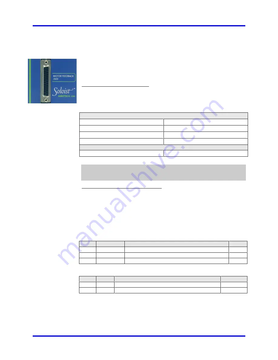
The Normally Open Brake Relay Contacts are accessible through TB206 and the Motor
Feedback connector (J103). The Brake Relay Normally Closed Contact is only accessible
through TB206 (see Figure 4-8). The Motor Feedback connector (J103) allows the brake
wires to be included in the motor feedback cable and eliminate the need for a separate
brake cable. The Brake Relay connections to TB206 are listed in Table 4-13 and the
Brake Relay connections to the Motor Feedback connector (J103) are listed in Table 4-
14.
Table 4-13.
Brake / Relay Connector Pin-out (TB206)
Pin #
Label
Description
In/Out
3
Relay-N.C.
Brake Relay Output Normally Closed Contact
Output
4
Relay-Com.
Brake Relay Output Common Contact
Output
5
Relay-N.O.
Brake Relay Output Normally Open Contact (See JP1)
Output
Table 4-14.
Brake / Relay Connector Pin-out (J103)
Pin #
Label
Description
In/Out/Bi.
13
BRK-
Brake- Relay Output Normally Open Contact (See JP1)
Output
25
BRK+
Brake+ Power connection (See JP1)
Output
Figure 4-8 is an example of a +24 VDC Brake connected to TB206. In this example, JP1
must be set 1-3 and all other jumpers removed. Otherwise, the user must connect J103 pin
13 to J103 pin 25. In this case, J103 would function as an interlock to prevent the Brake
from releasing, if the Motor Feedback connector is not connected.
Содержание SOLOIST
Страница 20: ...Introduction Soloist Hardware Manual 1 10 www aerotech com...
Страница 50: ...Technical Details Soloist Hardware Manual 3 6 www aerotech com Figure 3 3 User Outputs J104...
Страница 77: ...Soloist Hardware Manual Soloist Options www aerotech com 4 13 Figure 4 10 Suppression for DC Brake Systems...
Страница 78: ...Soloist Options Soloist Hardware Manual 4 14 www aerotech com...
Страница 88: ...Accessories Soloist Hardware Manual 5 10 www aerotech com...
Страница 96: ...Troubleshooting Soloist Hardware Manual 6 8 www aerotech com...
Страница 114: ...Index Soloist Hardware Manual iv www aerotech com...
Страница 116: ......


