Chapter 1
11
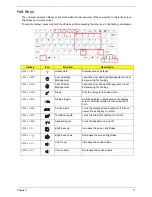
Hot Keys
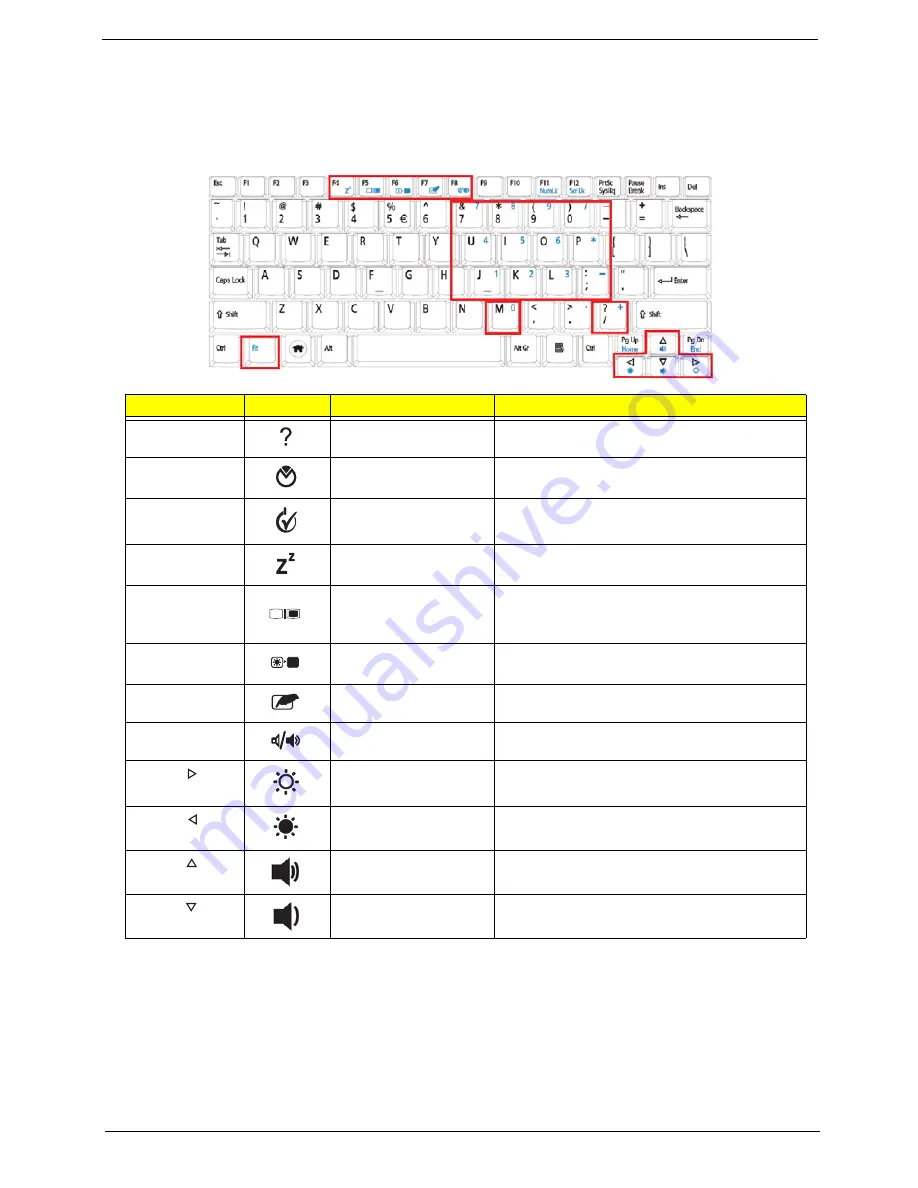
The computer employs hotkeys or key combinations to access most of the computer's controls like screen
brightness and volume output.
To activate hotkeys, press and hold the
<Fn>
key before pressing the other key in the hotkey combination.
Hotkey
Icon
Function
Description
<Fn> + <F1>
Hotkey help
Displays help on hotkeys.
<Fn> + <F2>
Acer eSettings
Management
Launches Acer eSettings Management in Acer
Empowering Technology.
<Fn> + <F3>
Acer ePower
Management
Launches Acer ePower Management in Acer
Empowering Technology.
<Fn> + <F4>
Sleep
Puts the computer in Sleep mode.
<Fn> + <F5>
Display toggle
Switches display output between the display
screen, external monitor (if connected) and
both.
<Fn> + <F6>
Screen blank
Turns the display screen backlight off to save
power. Press any key to return.
<Fn> + <F7>
TouchPad toggle
Turns the internal TouchPad on and off.
<Fn> + <F8>
Speaker toggle
Turns the speakers on and off.
<Fn> + < >
Brightness up
Increases the screen brightness.
<Fn> + < >
Brightness down
Decreases the screen brightness.
<Fn> + < >
Volume up
Increases the sound volume.
<Fn> + < >
Volume down
Decreases the sound volume.
Содержание Aspire One AOD150
Страница 6: ...VI ...
Страница 10: ...X Table of Contents ...
Страница 28: ...18 Chapter 1 ...
Страница 42: ...32 Chapter 2 5 Flash is complete when the message Flash programming complete displays ...
Страница 55: ...Chapter 3 45 4 Lift the Memory cover up to remove 5 Lift the WLAN cover up to remove ...
Страница 67: ...Chapter 3 57 7 Lift the Upper Cover clear of the computer ...
Страница 78: ...68 Chapter 3 4 Lift the USB Board clear of the computer rear edge first ...
Страница 80: ...70 Chapter 3 4 Turn the Bluetooth Module over and disconnect the Bluetooth cable ...
Страница 83: ...Chapter 3 73 9 Turn the Mainboard over and disconnect the Power Cable ...
Страница 85: ...Chapter 3 75 5 Remove the Speaker Module from the Lower Cover ...
Страница 106: ...96 Chapter 3 3 Press down around the edges of the bezel to secure it in place 4 Replace the four screws and screw caps ...
Страница 110: ...100 Chapter 3 4 Secure the Speaker Module cable in place with the adhesive strips ...
Страница 116: ...106 Chapter 3 8 The Lower Cover appears as follows when all the LCD cables are correctly placed ...
Страница 220: ...Appendix A 210 ...
Страница 228: ...218 Appendix C ...


