Chapter 3
41
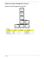
External Module Disassembly Process
External Modules Disassembly Flowchart
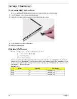
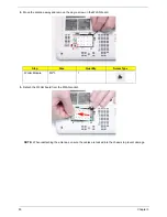
Screw List
Step
Screw
Quantity
Part No.
Lower Covers
M2*6
2
86.S5502.002
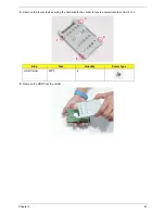
HDD Carrier
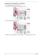
M3*3
4
86.S5502.003
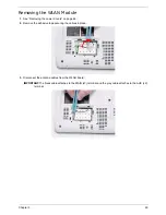
WLAN Module
M2*3
1
86.S5502.001
Disconnect power
and signal cables
from system
Remove
Battery
Turn off system
and peripherals
power
Remove
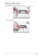
DIMM
Remove
WLAN
Remove
HDD
Remove
Lower Covers
Remove
Dummy Card
Содержание Aspire One AOD150
Страница 6: ...VI ...
Страница 10: ...X Table of Contents ...
Страница 28: ...18 Chapter 1 ...
Страница 42: ...32 Chapter 2 5 Flash is complete when the message Flash programming complete displays ...
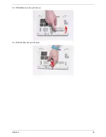
Страница 55: ...Chapter 3 45 4 Lift the Memory cover up to remove 5 Lift the WLAN cover up to remove ...
Страница 67: ...Chapter 3 57 7 Lift the Upper Cover clear of the computer ...
Страница 78: ...68 Chapter 3 4 Lift the USB Board clear of the computer rear edge first ...
Страница 80: ...70 Chapter 3 4 Turn the Bluetooth Module over and disconnect the Bluetooth cable ...
Страница 83: ...Chapter 3 73 9 Turn the Mainboard over and disconnect the Power Cable ...
Страница 85: ...Chapter 3 75 5 Remove the Speaker Module from the Lower Cover ...
Страница 106: ...96 Chapter 3 3 Press down around the edges of the bezel to secure it in place 4 Replace the four screws and screw caps ...
Страница 110: ...100 Chapter 3 4 Secure the Speaker Module cable in place with the adhesive strips ...
Страница 116: ...106 Chapter 3 8 The Lower Cover appears as follows when all the LCD cables are correctly placed ...
Страница 220: ...Appendix A 210 ...
Страница 228: ...218 Appendix C ...


