22
Chapter 2
Advanced
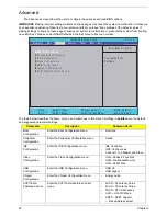
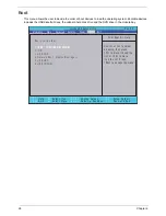
The Advanced screen allows the user to configure the various advanced BIOS options.
IMPORTANT:
Making incorrect settings to items on these pages may cause the system to malfunction. Unless you
have experience adjusting these items, we recommend that you leave these settings at the default values. If
making settings to items on these pages causes your system to malfunction or prevents the system from booting,
open BIOS and choose Load Optimal Defaults in the Exit menu to boot up normally.
The table below describes the items, menus, and submenus in this screen. Settings in
boldface
are the default
and suggested parameter settings.
Parameter
Description
Submenu Items
Boot
Configuration
Enter the Boot Configuration menu.
•
Numlock
Peripheral
Configuration
Enter the Peripheral Configuration menu.
•
Azalia
IDE
Configuration
Enter the IDE Configuration menu.
•
IDE Controller
•
HDC Configure as
•
Channel 1 to 4 Master and Slave
Video
Configuration
Enter the Video Configuration menu. •
IGD—Device2,
Function1
•
IGD—Pre-allocat Memory
•
IGD—DVMT Size
USB
Configuration
Enter the USB Configuration menu.
•
USB 2.0
•
USB Legacy
Chipset
Configuration
Enter the Chipset Configuration menu.
•
Energy Lake
ACPI Table/
Features Control
Enter the ACPI Table/Features Control
menu.
•
FACP—C2 Latency Value
•
FACP—C3 Latency Value
•
FACP—RTC S4 Wakeup
•
APIC—IO APIC Mode
•
HPET—HPET Support
• Base Address select
I t e m S p e c i f i c H e l p
C o n f i g u r e s B o o t
S e t t i n g s .
F 1
E S C
H e l p
E x i t
S e l e c t I t e m
S e l e c t M e n u
C h a n g e Va l u e s
S e l e c t
S u b M e n u
E n t e r
F 9
F 10
S e t u p D e f a u l t
S a v e a n d E x i t
X
B o o t C o n f i g u r a t i o n
X
P e r i p h e r a l C o n f i g u r a t i o n
X
I D E C o n f i g u r a t i o n
X
V i d e o C o n f i g u r a t i o n
X
U S B C o n f i g u r a t i o n
X
C h i p s e t C o n f i g u r a t i o n
X
A C P I T a b l e / F e a t u r e s C o n t r o l
X
B o o t C o n f i g u r a t i o n
X
P e r i p h e r a l C o n f i g u r a t i o n
X
I D E C o n f i g u r a t i o n
X
V i d e o C o n f i g u r a t i o n
X
U S B C o n f i g u r a t i o n
X
C h i p s e t C o n f i g u r a t i o n
X
A C P I T a b l e / F e a t u r e s C o n t r o l
F 5 / F 6
I n s y d e H 2 0 S e t u p U t i l i t y R e v . 3 . 5
Boot
Exit
Security
Information
Advanced
Power
Main
Содержание Aspire One AOD150
Страница 6: ...VI ...
Страница 10: ...X Table of Contents ...
Страница 28: ...18 Chapter 1 ...
Страница 42: ...32 Chapter 2 5 Flash is complete when the message Flash programming complete displays ...
Страница 55: ...Chapter 3 45 4 Lift the Memory cover up to remove 5 Lift the WLAN cover up to remove ...
Страница 67: ...Chapter 3 57 7 Lift the Upper Cover clear of the computer ...
Страница 78: ...68 Chapter 3 4 Lift the USB Board clear of the computer rear edge first ...
Страница 80: ...70 Chapter 3 4 Turn the Bluetooth Module over and disconnect the Bluetooth cable ...
Страница 83: ...Chapter 3 73 9 Turn the Mainboard over and disconnect the Power Cable ...
Страница 85: ...Chapter 3 75 5 Remove the Speaker Module from the Lower Cover ...
Страница 106: ...96 Chapter 3 3 Press down around the edges of the bezel to secure it in place 4 Replace the four screws and screw caps ...
Страница 110: ...100 Chapter 3 4 Secure the Speaker Module cable in place with the adhesive strips ...
Страница 116: ...106 Chapter 3 8 The Lower Cover appears as follows when all the LCD cables are correctly placed ...
Страница 220: ...Appendix A 210 ...
Страница 228: ...218 Appendix C ...


