Chapter 5
135
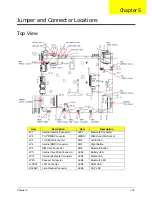
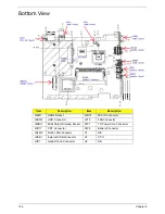
Jumper and Connector Locations
Top View
Item
Description
Item
Description
JP1
Internal camera Connector
JBT1
Bluetooth Connector
JP2
TO PWR/B Connector
JMINI2
MINI Card (3G) Socket
JP3
TO USB/B Connector
SW2
Left Button
JP4
Internal DMIC Connector
SW3
Right Button
JP5
SIM Card Connector
SW4
Bluetooth Button
JP11
Internal TouchPad Connector
LED2
Battery LED
JP12
Internal Keyboard Connector
LED3
Media LED
JP20
Speaker Connector
LED4
Bluetooth LED
JLVDS1
LCD Connector
LED5
NUM LED
JREAD1
Card Reader Connector
LED6
CAP LED
Chapter 5
Содержание Aspire One AOD150
Страница 6: ...VI ...
Страница 10: ...X Table of Contents ...
Страница 28: ...18 Chapter 1 ...
Страница 42: ...32 Chapter 2 5 Flash is complete when the message Flash programming complete displays ...
Страница 55: ...Chapter 3 45 4 Lift the Memory cover up to remove 5 Lift the WLAN cover up to remove ...
Страница 67: ...Chapter 3 57 7 Lift the Upper Cover clear of the computer ...
Страница 78: ...68 Chapter 3 4 Lift the USB Board clear of the computer rear edge first ...
Страница 80: ...70 Chapter 3 4 Turn the Bluetooth Module over and disconnect the Bluetooth cable ...
Страница 83: ...Chapter 3 73 9 Turn the Mainboard over and disconnect the Power Cable ...
Страница 85: ...Chapter 3 75 5 Remove the Speaker Module from the Lower Cover ...
Страница 106: ...96 Chapter 3 3 Press down around the edges of the bezel to secure it in place 4 Replace the four screws and screw caps ...
Страница 110: ...100 Chapter 3 4 Secure the Speaker Module cable in place with the adhesive strips ...
Страница 116: ...106 Chapter 3 8 The Lower Cover appears as follows when all the LCD cables are correctly placed ...
Страница 220: ...Appendix A 210 ...
Страница 228: ...218 Appendix C ...

