Chapter 2
29
Exit
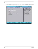
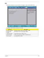
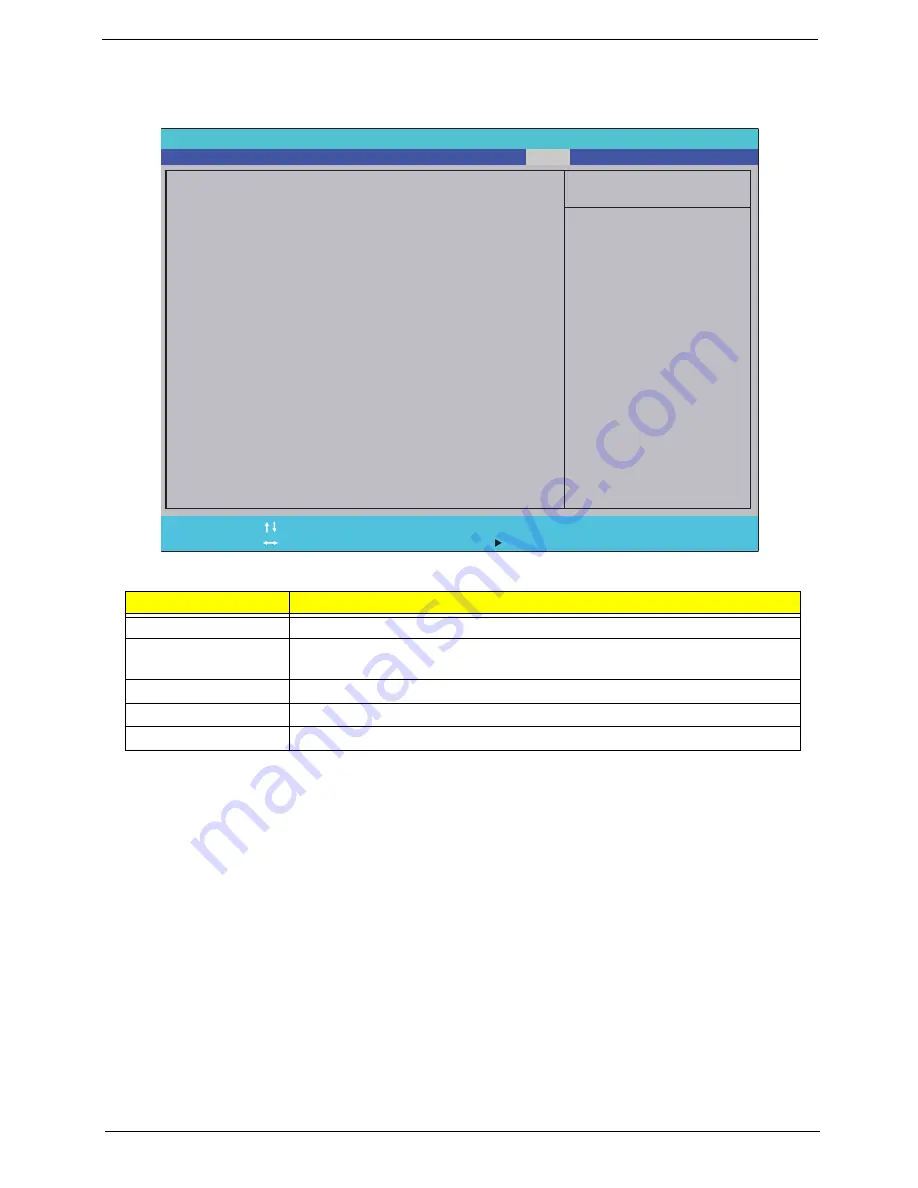
The Exit screen allows you to save or discard any changes you made and quit the BIOS Utility.
The table below describes the parameters in this screen.
Parameter
Description
Exit Saving Changes
Exit System Setup and save your changes to CMOS.
Exit Discarding
Changes
Exit utility without saving setup data to CMOS.
Load Setup Default
Load default values for all SETUP item.
Discard Changes
Load previous values from CMOS for all SETUP items.
Save Changes
Save Setup Data to CMOS.
I t e m S p e c i f i c H e l p
E x i t S y s t e m S e t u p a n d
s a v e y o u r c h a n g e s t o
C M O S .
F 1
E S C
H e l p
E x i t
S e l e c t I t e m
S e l e c t M e n u
C h a n g e Va l u e s
S e l e c t
S u b M e n u
E n t e r
F 9
F 10
S e t u p D e f a u l t
S a v e a n d E x i t
E x i t S a v i n g C h a n g e s
E x i t D i s c a r d i n g C h a n g e s
L o a d S e t u p D e f a u l t s
D i s c a r d C h a n g e s
S a v e C h a n g e s
E x i t S a v i n g C h a n g e s
E x i t D i s c a r d i n g C h a n g e s
L o a d S e t u p D e f a u l t s
D i s c a r d C h a n g e s
S a v e C h a n g e s
F 5 / F 6
I n s y d e H 2 0 S e t u p U t i l i t y R e v . 3 . 5
Information
Advanced
Main
Boot
Exit
Security
Power
Содержание Aspire One AOD150
Страница 6: ...VI ...
Страница 10: ...X Table of Contents ...
Страница 28: ...18 Chapter 1 ...
Страница 42: ...32 Chapter 2 5 Flash is complete when the message Flash programming complete displays ...
Страница 55: ...Chapter 3 45 4 Lift the Memory cover up to remove 5 Lift the WLAN cover up to remove ...
Страница 67: ...Chapter 3 57 7 Lift the Upper Cover clear of the computer ...
Страница 78: ...68 Chapter 3 4 Lift the USB Board clear of the computer rear edge first ...
Страница 80: ...70 Chapter 3 4 Turn the Bluetooth Module over and disconnect the Bluetooth cable ...
Страница 83: ...Chapter 3 73 9 Turn the Mainboard over and disconnect the Power Cable ...
Страница 85: ...Chapter 3 75 5 Remove the Speaker Module from the Lower Cover ...
Страница 106: ...96 Chapter 3 3 Press down around the edges of the bezel to secure it in place 4 Replace the four screws and screw caps ...
Страница 110: ...100 Chapter 3 4 Secure the Speaker Module cable in place with the adhesive strips ...
Страница 116: ...106 Chapter 3 8 The Lower Cover appears as follows when all the LCD cables are correctly placed ...
Страница 220: ...Appendix A 210 ...
Страница 228: ...218 Appendix C ...


