Chapter 1
5
Closed Front View
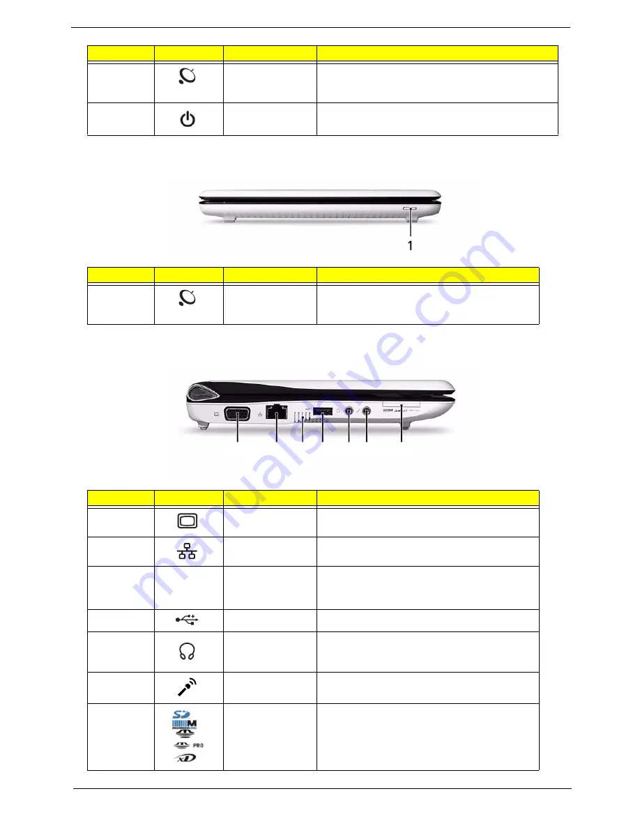
Left View
10
Wireless LAN
communication
indicator
Indicates the status of wireless LAN
communication.
11
Power button/
indicator
Turns the computer on and off.
No.
Icon
Item
Description
1
Wireless
communication
switch
Enables/disables the wireless function.
No.
Icon
Item
Description
1
External display
(VGA) port
Connects to a display device
(e.g. external monitor, projector).
2
Ethernet (RJ-45)
port
Connects to an Ethernet 10/100-based
network.
3
Ventilation slots
and cooling fan
Enable the computer to stay cool, even after
prolonged use.
Note:
Do not cover or obstruct the fan opening.
4
USB 2.0 port
Connect to USB 2.0 devices (e.g. USB mouse).
5
Headphones/
speaker/line-out
jack
Connects to line-out audio devices
(e.g. speakers, headphones).
6
Microphone-in
jack
Accepts input from external microphones.
7
Multi-in-1 card
reader
Accepts Secure Digital (SD), MultiMediaCard
(MMC), Memory Stick (MS), Memory Stick
PRO (MS PRO), xD-Picture Card (xD).
Note:
Push to remove/install the card. Only
one card can operate at any given time.
No.
Icon
Item
Description
1 2 3 4 5 6 7
Содержание Aspire One AOD150
Страница 6: ...VI ...
Страница 10: ...X Table of Contents ...
Страница 28: ...18 Chapter 1 ...
Страница 42: ...32 Chapter 2 5 Flash is complete when the message Flash programming complete displays ...
Страница 55: ...Chapter 3 45 4 Lift the Memory cover up to remove 5 Lift the WLAN cover up to remove ...
Страница 67: ...Chapter 3 57 7 Lift the Upper Cover clear of the computer ...
Страница 78: ...68 Chapter 3 4 Lift the USB Board clear of the computer rear edge first ...
Страница 80: ...70 Chapter 3 4 Turn the Bluetooth Module over and disconnect the Bluetooth cable ...
Страница 83: ...Chapter 3 73 9 Turn the Mainboard over and disconnect the Power Cable ...
Страница 85: ...Chapter 3 75 5 Remove the Speaker Module from the Lower Cover ...
Страница 106: ...96 Chapter 3 3 Press down around the edges of the bezel to secure it in place 4 Replace the four screws and screw caps ...
Страница 110: ...100 Chapter 3 4 Secure the Speaker Module cable in place with the adhesive strips ...
Страница 116: ...106 Chapter 3 8 The Lower Cover appears as follows when all the LCD cables are correctly placed ...
Страница 220: ...Appendix A 210 ...
Страница 228: ...218 Appendix C ...


