

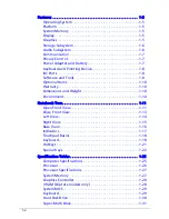


vi
DOS Flash Utility . . . . . . . . . . . . . . . . . . . . . . . . . . . . . . . . . . . .2-12
WinFlash Utility . . . . . . . . . . . . . . . . . . . . . . . . . . . . . . . . . . . .2-12
Remove HDD/BIOS Password Utilities. . . . . . . . . . . . . . . . . . . . . 2-13
Removing the HDD Password . . . . . . . . . . . . . . . . . . . . . . . . .2-13
Removing the BIOS Passwords. . . . . . . . . . . . . . . . . . . . . . . . .2-14
Clearing the BIOS Passwords . . . . . . . . . . . . . . . . . . . . . . . . . .2-15
Using DMI Tools . . . . . . . . . . . . . . . . . . . . . . . . . . . . . . . . . . . . . . 2-16
LAN EEPROM Utility . . . . . . . . . . . . . . . . . . . . . . . . . . . . . . . . .2-16
CHAPTER 3
Machine Maintenance
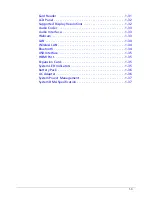
Machine Disassembly and Replacement. . . . . . . . . . . . . . . . . . . 3-5
Recommended Equipment . . . . . . . . . . . . . . . . . . . . . . . . . . .3-5
Replacement Requirements. . . . . . . . . . . . . . . . . . . . . . . . . . .3-5
Pre-disassembly Instructions . . . . . . . . . . . . . . . . . . . . . . . . . .3-6
Disassembly Process . . . . . . . . . . . . . . . . . . . . . . . . . . . . . . . . . . . 3-7
External Module Disassembly Process. . . . . . . . . . . . . . . . . . . . . 3-8
External Modules Disassembly Flowchart . . . . . . . . . . . . . . . .3-8
Removing the Battery Pack . . . . . . . . . . . . . . . . . . . . . . . . . . .3-9
Remove the Dummy Card . . . . . . . . . . . . . . . . . . . . . . . . . . . .3-10
Removing the ODD Module . . . . . . . . . . . . . . . . . . . . . . . . . .3-11
Removing the Base Door . . . . . . . . . . . . . . . . . . . . . . . . . . . . .3-13
Removing the HDD Module. . . . . . . . . . . . . . . . . . . . . . . . . . .3-14
Removing the WLAN Module . . . . . . . . . . . . . . . . . . . . . . . . .3-16
Removing the Memory Modules . . . . . . . . . . . . . . . . . . . . . . .3-17
Main Unit Disassembly Process . . . . . . . . . . . . . . . . . . . . . . . . . . 3-19
Main Unit Disassembly Flowchart . . . . . . . . . . . . . . . . . . . . . .3-19
Removing the Keyboard . . . . . . . . . . . . . . . . . . . . . . . . . . . . .3-20
Removing the Palmrest Module/Upper Cover . . . . . . . . . . . .3-23
Removing the Speakers . . . . . . . . . . . . . . . . . . . . . . . . . . . . . .3-27
Removing the Power Button Board . . . . . . . . . . . . . . . . . . . .3-29
Removing the Touchpad Board. . . . . . . . . . . . . . . . . . . . . . . .3-31
Removing the USB Board. . . . . . . . . . . . . . . . . . . . . . . . . . . . .3-33
Removing the Bluetooth Module . . . . . . . . . . . . . . . . . . . . . .3-35
Removing the Mainboard . . . . . . . . . . . . . . . . . . . . . . . . . . . .3-36
Removing the Thermal Module. . . . . . . . . . . . . . . . . . . . . . . .3-38
Removing the CPU . . . . . . . . . . . . . . . . . . . . . . . . . . . . . . . . . .3-40
Removing the LCD Module . . . . . . . . . . . . . . . . . . . . . . . . . . .3-41
Содержание Aspire 4560
Страница 1: ... Aspire 4560 4560G SERVICEGUIDE ...
Страница 10: ...x ...
Страница 11: ...CHAPTER 1 Hardware Specifications ...
Страница 14: ...1 4 ...
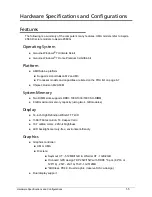
Страница 34: ...1 24 Hardware Specifications and Configurations System Block Diagram Figure 1 12 System Block Diagram ...
Страница 51: ...CHAPTER 2 System Utilities ...
Страница 67: ...CHAPTER 3 Machine Maintenance ...
Страница 70: ...3 4 ...
Страница 100: ...3 34 Machine Maintenance 4 Remove the USB board from the lower case Figure 3 44 USB Board ...
Страница 105: ...Machine Maintenance 3 39 4 Remove the thermal module from the mainboard Figure 3 53 Thermal Module ...
Страница 109: ...Machine Maintenance 3 43 6 Remove the LCD module from the lower cover Figure 3 60 LCD Module ...
Страница 128: ...3 62 Machine Maintenance 3 Secure the bezel with the two 2 screw covers Figure 3 90 LCD Bezel Screw Covers ...
Страница 162: ...3 96 Machine Maintenance ...
Страница 163: ...CHAPTER 4 Troubleshooting ...
Страница 193: ...CHAPTER 5 Jumper and Connector Locations ...
Страница 200: ...5 8 Jumper and Connector Locations ...
Страница 201: ...CHAPTER 6 FRU List ...
Страница 202: ...6 2 Aspire 4560 4560G Exploded Diagram 6 4 Main Assembly 6 4 LCD Assembly 6 6 FRU List 6 7 ...
Страница 217: ...CHAPTER 7 Model Definition and Configuration ...
Страница 218: ...7 2 Aspire 4560 4560G 7 3 ...
Страница 325: ...CHAPTER 8 Test Compatible Components ...
Страница 326: ...8 2 Microsoft Windows 7 Environment Test 8 4 ...
Страница 332: ...8 8 Test Compatible Components ...
Страница 333: ...CHAPTER 9 Online Support Information ...
Страница 334: ...9 2 Online Support Information 9 3 ...
Страница 336: ...9 4 Online Support Information ...


