


5-6
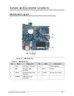
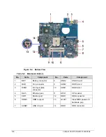
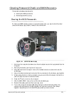
Jumper and Connector Locations
10. Press
F9
to load the system defaults.
11. Press
F10
to save the changes you made and close the Setup Utility.
12. If a wireless module was removed, reinstall it.
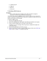
Performing a BIOS Recovery
0
Boot Block
0
An interruption during a BIOS flash procedure (e.g. a power outage) can corrupt the BIOS
code, which will cause the system to go into an unbootable state. The BIOS boot block refers
to a special BIOS program that can be used to boot up a system with minimum BIOS
initialization.You need to access and execute the boot block to reboot the computer and
recover the regular BIOS code.
Creating the Crisis Disk
0
NOTE:
NOTE
:
The BIOS crisis recovery disk should be prepared in a computer running the Windows
XP, Vista, or 7 OS.
1. Prepare a removable USB flash drive.
Note that all data in the USB flash drive will be cleared during the creation of the crisis
disk.
2. Set up a computer running the Windows XP, Vista, or 7 operating system and plug in the
USB flash drive into an available USB port.
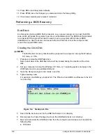
3. Open the
Notepad
program and create a new file.
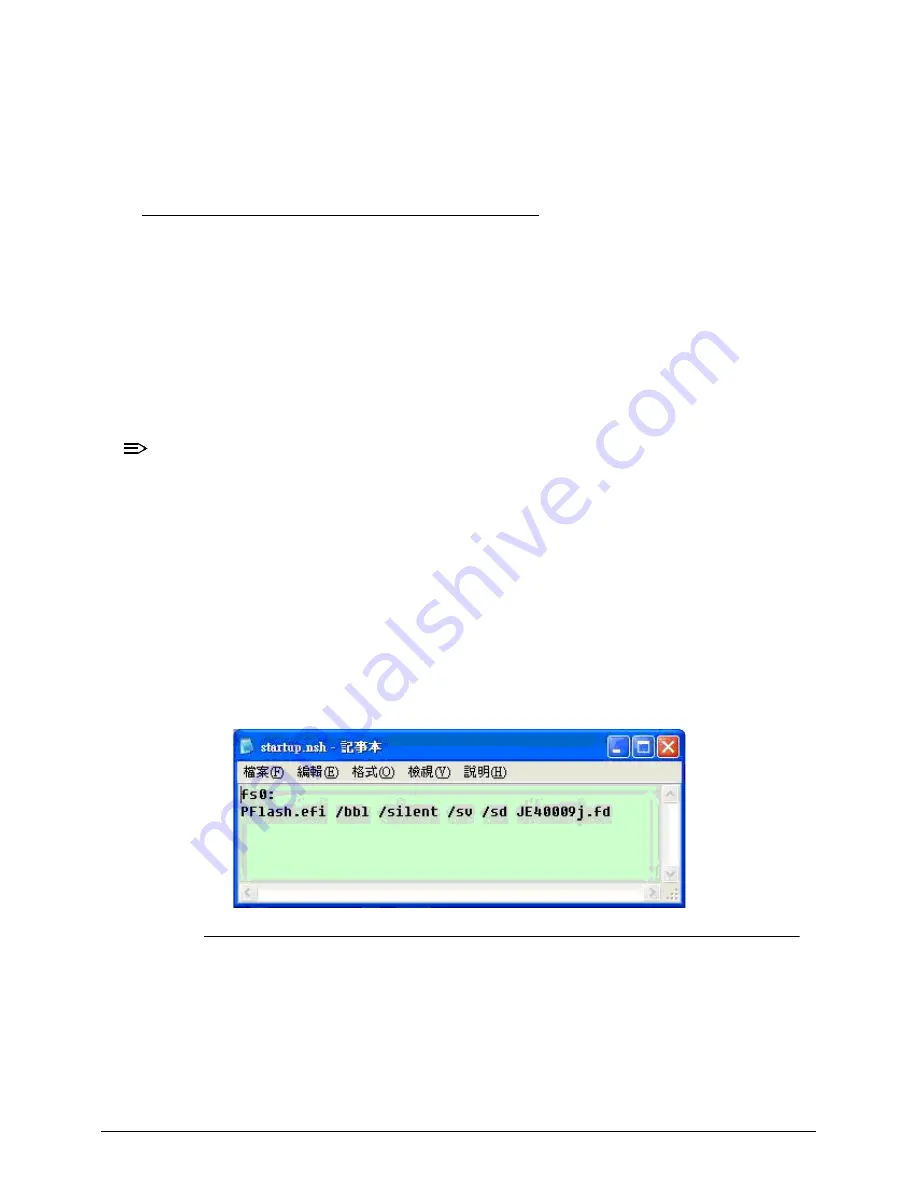
4. Type
startup.nsh
.
For example, the USB key prompt is
fs0
. The
PFlash.efi
and
BIOS.cap
files are in the
fs0:
root directory
.
Figure 5-4. Startup.nsh File
5. Save this file as
startup.nsh
in the USB flash drive’s root directory.
6. Decompress the Crisis Package Source in the USB flash drive’s root directory.
7. Eject and reconnect the USB flash drive from the computer, and make sure it contains the
following files:
EFI folder
Содержание Aspire 4560
Страница 1: ... Aspire 4560 4560G SERVICEGUIDE ...
Страница 10: ...x ...
Страница 11: ...CHAPTER 1 Hardware Specifications ...
Страница 14: ...1 4 ...
Страница 34: ...1 24 Hardware Specifications and Configurations System Block Diagram Figure 1 12 System Block Diagram ...
Страница 51: ...CHAPTER 2 System Utilities ...
Страница 67: ...CHAPTER 3 Machine Maintenance ...
Страница 70: ...3 4 ...
Страница 100: ...3 34 Machine Maintenance 4 Remove the USB board from the lower case Figure 3 44 USB Board ...
Страница 105: ...Machine Maintenance 3 39 4 Remove the thermal module from the mainboard Figure 3 53 Thermal Module ...
Страница 109: ...Machine Maintenance 3 43 6 Remove the LCD module from the lower cover Figure 3 60 LCD Module ...
Страница 128: ...3 62 Machine Maintenance 3 Secure the bezel with the two 2 screw covers Figure 3 90 LCD Bezel Screw Covers ...
Страница 162: ...3 96 Machine Maintenance ...
Страница 163: ...CHAPTER 4 Troubleshooting ...
Страница 193: ...CHAPTER 5 Jumper and Connector Locations ...
Страница 200: ...5 8 Jumper and Connector Locations ...
Страница 201: ...CHAPTER 6 FRU List ...
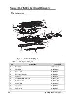
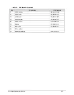
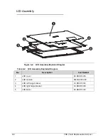
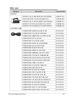
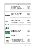
Страница 202: ...6 2 Aspire 4560 4560G Exploded Diagram 6 4 Main Assembly 6 4 LCD Assembly 6 6 FRU List 6 7 ...
Страница 217: ...CHAPTER 7 Model Definition and Configuration ...
Страница 218: ...7 2 Aspire 4560 4560G 7 3 ...
Страница 325: ...CHAPTER 8 Test Compatible Components ...
Страница 326: ...8 2 Microsoft Windows 7 Environment Test 8 4 ...
Страница 332: ...8 8 Test Compatible Components ...
Страница 333: ...CHAPTER 9 Online Support Information ...
Страница 334: ...9 2 Online Support Information 9 3 ...
Страница 336: ...9 4 Online Support Information ...


