

Troubleshooting
4-21
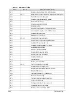
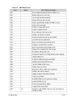
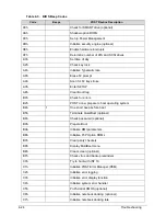
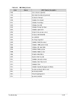
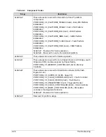
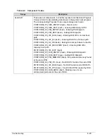
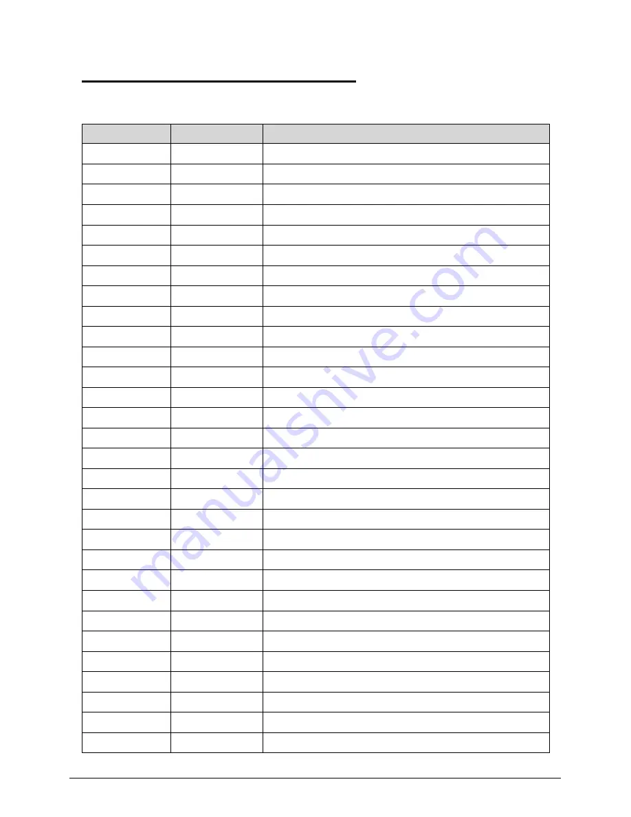
BIOS Beep Codes
0
Table 4-3. BIOS Beep Codes
Code
Beeps
POST Routine Description
02h
Verify Real Mode
03h
Disable Non-Maskable Interrupt (NMI)
04h
Get CPU type
06h
Initialize system hardware
08h
Initialize chipset with initial POST values
09h
Set IN POST flag
0Ah
Initialize CPU registers
0Bh
Enable CPU cache
0Ch
Initialize caches to initial POST values
0Eh
Initialize I/O component
0Fh
Initialize the local bus IDE
10h
Initialize Power Management
11h
Load alternate registers with initial POST values
12h
Restore CPU control word during warm boot
13h
Initialize PCI Bus Mastering devices
14h
Initialize keyboard controller
16h
1-2-2-3
BIOS ROM checksum
17h
Initialize cache before memory autosize
18h
8254 timer initialization
1Ah
8237 DMA controller initialization
1Ch
Reset Programmable Interrupt Controller
20h
1-3-1-1
Test DRAM refresh
22h
1-3-1-3
Test 8742 Keyboard Controller
24h
Set ES segment register to 4 GB
26h
Enable A20 line
28h
Autosize DRAM
29h
Initialize POST Memory Manager
2Ah
Clear 215 KB base RAM
2Ch
1-3-4-1
RAM failure on address line xxxx
2Eh
1-3-4-3
RAM failure on data bits xxxx of low byte of memory bus
Содержание Aspire 4560
Страница 1: ... Aspire 4560 4560G SERVICEGUIDE ...
Страница 10: ...x ...
Страница 11: ...CHAPTER 1 Hardware Specifications ...
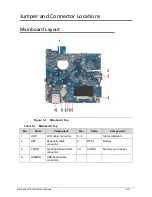
Страница 14: ...1 4 ...
Страница 34: ...1 24 Hardware Specifications and Configurations System Block Diagram Figure 1 12 System Block Diagram ...
Страница 51: ...CHAPTER 2 System Utilities ...
Страница 67: ...CHAPTER 3 Machine Maintenance ...
Страница 70: ...3 4 ...
Страница 100: ...3 34 Machine Maintenance 4 Remove the USB board from the lower case Figure 3 44 USB Board ...
Страница 105: ...Machine Maintenance 3 39 4 Remove the thermal module from the mainboard Figure 3 53 Thermal Module ...
Страница 109: ...Machine Maintenance 3 43 6 Remove the LCD module from the lower cover Figure 3 60 LCD Module ...
Страница 128: ...3 62 Machine Maintenance 3 Secure the bezel with the two 2 screw covers Figure 3 90 LCD Bezel Screw Covers ...
Страница 162: ...3 96 Machine Maintenance ...
Страница 163: ...CHAPTER 4 Troubleshooting ...
Страница 193: ...CHAPTER 5 Jumper and Connector Locations ...
Страница 200: ...5 8 Jumper and Connector Locations ...
Страница 201: ...CHAPTER 6 FRU List ...
Страница 202: ...6 2 Aspire 4560 4560G Exploded Diagram 6 4 Main Assembly 6 4 LCD Assembly 6 6 FRU List 6 7 ...
Страница 217: ...CHAPTER 7 Model Definition and Configuration ...
Страница 218: ...7 2 Aspire 4560 4560G 7 3 ...
Страница 325: ...CHAPTER 8 Test Compatible Components ...
Страница 326: ...8 2 Microsoft Windows 7 Environment Test 8 4 ...
Страница 332: ...8 8 Test Compatible Components ...
Страница 333: ...CHAPTER 9 Online Support Information ...
Страница 334: ...9 2 Online Support Information 9 3 ...
Страница 336: ...9 4 Online Support Information ...


