


4-24
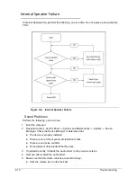
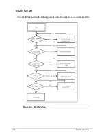
Troubleshooting
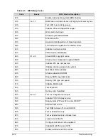
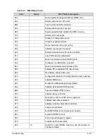
99h
Check for SMART drive (optional)
9Ah
Shadow option ROMs
9Ch
Set up Power Management
9Dh
Initialize security engine (optional)
9Eh
Enable hardware interrupts
9Fh
Determine number of ATA and SCSI drives
A0h
Set time of day
A2h
Check key lock
A4h
Initialize Typematic rate
A8h
Erase F2 prompt
AAh
Scan for F2 key stroke
ACh
Enter SETUP
AEh
Clear Boot flag
B0h
Check for errors
B2h
POST done- prepare to boot operating system
B4h
1
One short beep before boot
B5h
Terminate QuietBoot (optional)
B6h
Check password (optional)
B9h
Prepare Boot
BAh
Initialize DMI parameters
BBh
Initialize PnP Option ROMs
BCh
Clear parity checkers
BDh
Display MultiBoot menu
BEh
Clear screen (optional)
BFh
Check virus and backup reminders
C0h
Try to boot with INT 19
C1h
Initialize POST Error Manager (PEM)
C2h
Initialize error logging
C3h
Initialize error display function
C4h
Initialize system error handler
C5h
PnPnd dual CMOS (optional)
C6h
Initialize notebook docking (optional)
C7h
Initialize notebook docking late
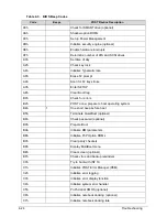
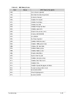
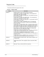
Table 4-3. BIOS Beep Codes
Code
Beeps
POST Routine Description
Содержание Aspire 4560
Страница 1: ... Aspire 4560 4560G SERVICEGUIDE ...
Страница 10: ...x ...
Страница 11: ...CHAPTER 1 Hardware Specifications ...
Страница 14: ...1 4 ...
Страница 34: ...1 24 Hardware Specifications and Configurations System Block Diagram Figure 1 12 System Block Diagram ...
Страница 51: ...CHAPTER 2 System Utilities ...
Страница 67: ...CHAPTER 3 Machine Maintenance ...
Страница 70: ...3 4 ...
Страница 100: ...3 34 Machine Maintenance 4 Remove the USB board from the lower case Figure 3 44 USB Board ...
Страница 105: ...Machine Maintenance 3 39 4 Remove the thermal module from the mainboard Figure 3 53 Thermal Module ...
Страница 109: ...Machine Maintenance 3 43 6 Remove the LCD module from the lower cover Figure 3 60 LCD Module ...
Страница 128: ...3 62 Machine Maintenance 3 Secure the bezel with the two 2 screw covers Figure 3 90 LCD Bezel Screw Covers ...
Страница 162: ...3 96 Machine Maintenance ...
Страница 163: ...CHAPTER 4 Troubleshooting ...
Страница 193: ...CHAPTER 5 Jumper and Connector Locations ...
Страница 200: ...5 8 Jumper and Connector Locations ...
Страница 201: ...CHAPTER 6 FRU List ...
Страница 202: ...6 2 Aspire 4560 4560G Exploded Diagram 6 4 Main Assembly 6 4 LCD Assembly 6 6 FRU List 6 7 ...
Страница 217: ...CHAPTER 7 Model Definition and Configuration ...
Страница 218: ...7 2 Aspire 4560 4560G 7 3 ...
Страница 325: ...CHAPTER 8 Test Compatible Components ...
Страница 326: ...8 2 Microsoft Windows 7 Environment Test 8 4 ...
Страница 332: ...8 8 Test Compatible Components ...
Страница 333: ...CHAPTER 9 Online Support Information ...
Страница 334: ...9 2 Online Support Information 9 3 ...
Страница 336: ...9 4 Online Support Information ...


