


4-26
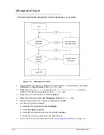
Troubleshooting
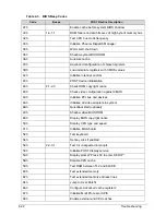
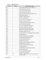
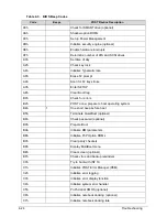
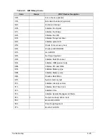
POST Codes
0
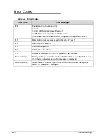
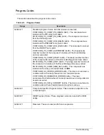
There are two types of POST codes: Progress Codes and Error Codes. Progress Codes are
designed to show the execution point while booting or executing services. Error Codes are
designed to halt on exceptional (fatal) error conditions.
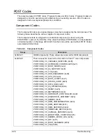
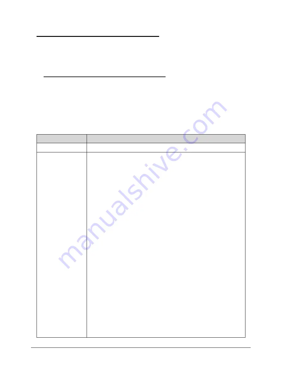
Component Codes
0
The Component Code is an unsigned integer value that is assigned by the build process. The
following tables describe the various ranges of component codes:
The Component Code is assigned to an individual component (or driver) using the
POSTCODE= option in the DSC file. If the value that follows POSTCODE= is a hexadecimal
or decimal number, in the range 0x00-0xdf, then that code will be used with all POST Codes
associated with that driver.
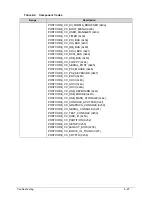
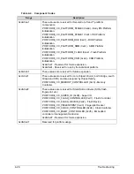
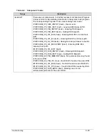
Table 4-4. Component Codes
Range
Description
0x00-0x1f
OEM Components. These values are reserved for OEM components
0x20-0x9f
These values are reserved for SecureCore Tiano™ core components.
POSTCODE_CC_VARIABLE_SERVICES (0x20)
POSTCODE_CC_KEYBOARD_CONTROLLER (0x21)
POSTCODE_CC_BOOT_MODE (0x22)
POSTCODE_CC_S3_SUPPORT (0x23)
POSTCODE_CC_TCG (0x24)
POSTCODE_CC_HDD_PASSWORD (0x25)
POSTCODE_CC_CPU_IO (0x26)
POSTCODE_CC_BOOT_SCRIPT (0x27)
POSTCODE_CC_STATUS_CODE (0x28)
POSTCODE_CC_DATA_HUB (0x29)
POSTCODE_CC_HII_DATABASE (0x2a)
POSTCODE_CC_RESET (0x2b)
POSTCODE_CC_METRONOME (0x2c)
POSTCODE_CC_INTERRUPT_CONTROLLER (0x2d)
POSTCODE_CC_DIAGNOSTIC_SUMMARY (0x2e)
POSTCODE_CC_SMBIOS (0x2f)
POSTCODE_CC_SMM_COMMUNICATION (0x30)
POSTCODE_CC_SMM_RUNTIME (0x31)
POSTCODE_CC_SMM_SERVICES (0x32)
POSTCODE_CC_FIRMWARE_DEVICE (0x33)
POSTCODE_CC_CAPSULE_SERVICES (0x34)
POSTCODE_CC_MONOTONIC_COUNTER (0x35)
POSTCODE_CC_SMBIOS_EVENT_LOG (0x36)
POSTCODE_CC_RTC (0x37)
POSTCODE_CC_BOOT_MANAGER (0x38)
POSTCODE_CC_VGA (0x39)
Содержание Aspire 4560
Страница 1: ... Aspire 4560 4560G SERVICEGUIDE ...
Страница 10: ...x ...
Страница 11: ...CHAPTER 1 Hardware Specifications ...
Страница 14: ...1 4 ...
Страница 34: ...1 24 Hardware Specifications and Configurations System Block Diagram Figure 1 12 System Block Diagram ...
Страница 51: ...CHAPTER 2 System Utilities ...
Страница 67: ...CHAPTER 3 Machine Maintenance ...
Страница 70: ...3 4 ...
Страница 100: ...3 34 Machine Maintenance 4 Remove the USB board from the lower case Figure 3 44 USB Board ...
Страница 105: ...Machine Maintenance 3 39 4 Remove the thermal module from the mainboard Figure 3 53 Thermal Module ...
Страница 109: ...Machine Maintenance 3 43 6 Remove the LCD module from the lower cover Figure 3 60 LCD Module ...
Страница 128: ...3 62 Machine Maintenance 3 Secure the bezel with the two 2 screw covers Figure 3 90 LCD Bezel Screw Covers ...
Страница 162: ...3 96 Machine Maintenance ...
Страница 163: ...CHAPTER 4 Troubleshooting ...
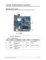
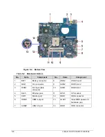
Страница 193: ...CHAPTER 5 Jumper and Connector Locations ...
Страница 200: ...5 8 Jumper and Connector Locations ...
Страница 201: ...CHAPTER 6 FRU List ...
Страница 202: ...6 2 Aspire 4560 4560G Exploded Diagram 6 4 Main Assembly 6 4 LCD Assembly 6 6 FRU List 6 7 ...
Страница 217: ...CHAPTER 7 Model Definition and Configuration ...
Страница 218: ...7 2 Aspire 4560 4560G 7 3 ...
Страница 325: ...CHAPTER 8 Test Compatible Components ...
Страница 326: ...8 2 Microsoft Windows 7 Environment Test 8 4 ...
Страница 332: ...8 8 Test Compatible Components ...
Страница 333: ...CHAPTER 9 Online Support Information ...
Страница 334: ...9 2 Online Support Information 9 3 ...
Страница 336: ...9 4 Online Support Information ...


