


4-28
Troubleshooting
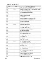
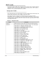
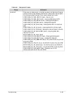
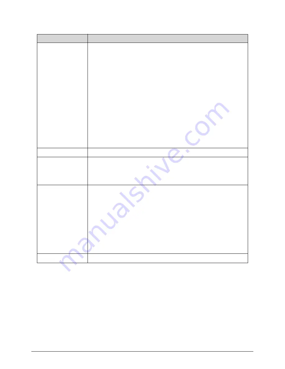
0xa0-0xaf
These values are reserved for SecureCore Tiano™ platform
components.
POSTCODE_CC_PLATFORM_STAGE0 (0xa0) - Early PEI Platform
Initialization.
POSTCODE_CC_PLATFORM_STAGE1 (0xa1) -PEI Platform
Initialization.
POSTCODE_CC_PLATFORM_DXE (0xa1) - DXE Platform
Initialization.
POSTCODE_CC_PLATFORM_SMM (0xa1) - SMM Platform
Initialization.
POSTCODE_CC_PLATFORM_FLASH (0xa2) - Flash Platform
Initialization.
POSTCODE_CC_PLATFORM_CSM (0xa3) - CSM Platform
Initialization.
0xa4-0xa7 - Reserved for future expansion.
0xa8-0xaf - Reserved for use by the individual platform.
0xb0-0xbf
These values are reserved for future expansion.
0xc0-0xcf
These values are reserved for core chipset drivers (north bridge, south
bridge and CPU) and are assigned by chipset family.
POSTCODE_CC_MEMORY_CONTROLLER (0xc0) - Memory
Controller.
0xd0-0xd7
These values are reserved for Small Silicon drivers (SIOs, flash,
fingerprint, etc.)
POSTCODE_CC_SUPER_IO (0xd0) - Super I/O
POSTCODE_CC_FLASH_CONTROLLER (0xd1) - Flash Controller
POSTCODE_CC_FLASH_DEVICE (0xd2) - Flash Device
POSTCODE_CC_FINGERPRINT (0xd3) - Fingerprint Sensor
POSTCODE_CC_CLOCK_CONTROLLER (0xd4) - Clock Controller
POSTCODE_CC_MGMT_CONTROLLER (0xd5) - Embedded
controller or management controller.
0xd6-0xd7 - Reserved for future expansion.
0xd8-0xdf
Reserved for platform usage.
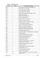
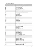
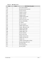
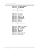
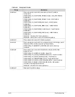
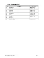
Table 4-4. Component Codes
Range
Description
Содержание Aspire 4560
Страница 1: ... Aspire 4560 4560G SERVICEGUIDE ...
Страница 10: ...x ...
Страница 11: ...CHAPTER 1 Hardware Specifications ...
Страница 14: ...1 4 ...
Страница 34: ...1 24 Hardware Specifications and Configurations System Block Diagram Figure 1 12 System Block Diagram ...
Страница 51: ...CHAPTER 2 System Utilities ...
Страница 67: ...CHAPTER 3 Machine Maintenance ...
Страница 70: ...3 4 ...
Страница 100: ...3 34 Machine Maintenance 4 Remove the USB board from the lower case Figure 3 44 USB Board ...
Страница 105: ...Machine Maintenance 3 39 4 Remove the thermal module from the mainboard Figure 3 53 Thermal Module ...
Страница 109: ...Machine Maintenance 3 43 6 Remove the LCD module from the lower cover Figure 3 60 LCD Module ...
Страница 128: ...3 62 Machine Maintenance 3 Secure the bezel with the two 2 screw covers Figure 3 90 LCD Bezel Screw Covers ...
Страница 162: ...3 96 Machine Maintenance ...
Страница 163: ...CHAPTER 4 Troubleshooting ...
Страница 193: ...CHAPTER 5 Jumper and Connector Locations ...
Страница 200: ...5 8 Jumper and Connector Locations ...
Страница 201: ...CHAPTER 6 FRU List ...
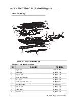
Страница 202: ...6 2 Aspire 4560 4560G Exploded Diagram 6 4 Main Assembly 6 4 LCD Assembly 6 6 FRU List 6 7 ...
Страница 217: ...CHAPTER 7 Model Definition and Configuration ...
Страница 218: ...7 2 Aspire 4560 4560G 7 3 ...
Страница 325: ...CHAPTER 8 Test Compatible Components ...
Страница 326: ...8 2 Microsoft Windows 7 Environment Test 8 4 ...
Страница 332: ...8 8 Test Compatible Components ...
Страница 333: ...CHAPTER 9 Online Support Information ...
Страница 334: ...9 2 Online Support Information 9 3 ...
Страница 336: ...9 4 Online Support Information ...


