

Hardware Specifications and Configurations
1-17
Indicators
0
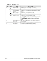
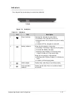
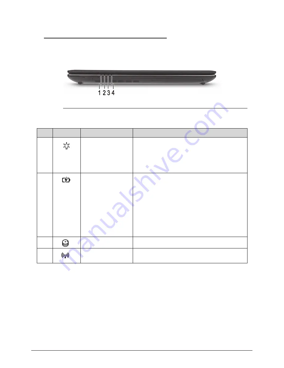
The computer has several easy-to-read status indicators.
Figure 1-6. Indicators
Table 1-6. Indicators
Icon
Item
Description
1
Power indicator
Indicates the computer’s power status.
Solid blue: The computer is turned on.
Blinking amber: The computer is in power-saving
mode.
Indicator off: The computer is turned off.
2
Battery indicator
When the AC adapter is connected:
Solid blue: The battery charge is at full capacity.
Solid amber: Battery charging.
Blinking amber: Battery is in abnormal stop
charge or battery is in low power state.
When the AC adapter is disconnected:
Blinking amber: Battery charge is in critically low
state
Indicator off: Discharging state.
3
HDD indicator
Flashes blue when there is hard drive activity.
4
Communication
indicator
Flashes amber when there is an active wireless
connection.
Содержание Aspire 4560
Страница 1: ... Aspire 4560 4560G SERVICEGUIDE ...
Страница 10: ...x ...
Страница 11: ...CHAPTER 1 Hardware Specifications ...
Страница 14: ...1 4 ...
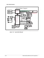
Страница 34: ...1 24 Hardware Specifications and Configurations System Block Diagram Figure 1 12 System Block Diagram ...
Страница 51: ...CHAPTER 2 System Utilities ...
Страница 67: ...CHAPTER 3 Machine Maintenance ...
Страница 70: ...3 4 ...
Страница 100: ...3 34 Machine Maintenance 4 Remove the USB board from the lower case Figure 3 44 USB Board ...
Страница 105: ...Machine Maintenance 3 39 4 Remove the thermal module from the mainboard Figure 3 53 Thermal Module ...
Страница 109: ...Machine Maintenance 3 43 6 Remove the LCD module from the lower cover Figure 3 60 LCD Module ...
Страница 128: ...3 62 Machine Maintenance 3 Secure the bezel with the two 2 screw covers Figure 3 90 LCD Bezel Screw Covers ...
Страница 162: ...3 96 Machine Maintenance ...
Страница 163: ...CHAPTER 4 Troubleshooting ...
Страница 193: ...CHAPTER 5 Jumper and Connector Locations ...
Страница 200: ...5 8 Jumper and Connector Locations ...
Страница 201: ...CHAPTER 6 FRU List ...
Страница 202: ...6 2 Aspire 4560 4560G Exploded Diagram 6 4 Main Assembly 6 4 LCD Assembly 6 6 FRU List 6 7 ...
Страница 217: ...CHAPTER 7 Model Definition and Configuration ...
Страница 218: ...7 2 Aspire 4560 4560G 7 3 ...
Страница 325: ...CHAPTER 8 Test Compatible Components ...
Страница 326: ...8 2 Microsoft Windows 7 Environment Test 8 4 ...
Страница 332: ...8 8 Test Compatible Components ...
Страница 333: ...CHAPTER 9 Online Support Information ...
Страница 334: ...9 2 Online Support Information 9 3 ...
Страница 336: ...9 4 Online Support Information ...


