

Troubleshooting
4-19
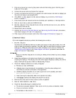
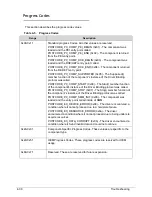
Intermittent Problems
0
Intermittent system hang problems can be caused by a variety of reasons that have nothing to
do with a hardware defect, such as: cosmic radiation, electrostatic discharge, or software
errors. FRU replacement should be considered only when a recurring problem exists.
When analyzing an intermittent problem, perform the following:
1. Run the advanced diagnostic test for the system board in loop mode at least 10 times.
2. If no error is detected, do not replace any FRU.
3. If an error is detected, replace the FRU. Rerun the test to verify that there are no more
errors.
Undetermined Problems
0
The diagnostic problems does not identify which adapter or device failed, which installed
devices are incorrect, whether a short circuit is suspected, or whether the system is
inoperative.
Perform the following procedures to isolate the failing FRU (do not isolate non-defective
FRU).
NOTE:
NOTE
:
Verify that all attached devices are supported by the computer.
NOTE:
NOTE
:
Verify that the power supply being used at the time of the failure is operating correctly.
1. Remove power from the computer.
2. Visually check the components for damage. If any problems are found, replace the FRU.
3. Remove or disconnect all of the following devices:
Non-Acer devices
Printer, mouse, and other external devices
Battery pack
Hard disk drive
DIMM
CD-ROM/Diskette drive Module
PC Cards
4. Apply power to the computer.
5. Determine if the problem has changed.
6. If the problem does not recur, connect the removed devices one at a time until failing FRU
is found.
7. If the problem remains, replace the following FRUs one at a time. Do not replace a
non-defective FRU:
Mainboard
LCD assembly
Содержание Aspire 4560
Страница 1: ... Aspire 4560 4560G SERVICEGUIDE ...
Страница 10: ...x ...
Страница 11: ...CHAPTER 1 Hardware Specifications ...
Страница 14: ...1 4 ...
Страница 34: ...1 24 Hardware Specifications and Configurations System Block Diagram Figure 1 12 System Block Diagram ...
Страница 51: ...CHAPTER 2 System Utilities ...
Страница 67: ...CHAPTER 3 Machine Maintenance ...
Страница 70: ...3 4 ...
Страница 100: ...3 34 Machine Maintenance 4 Remove the USB board from the lower case Figure 3 44 USB Board ...
Страница 105: ...Machine Maintenance 3 39 4 Remove the thermal module from the mainboard Figure 3 53 Thermal Module ...
Страница 109: ...Machine Maintenance 3 43 6 Remove the LCD module from the lower cover Figure 3 60 LCD Module ...
Страница 128: ...3 62 Machine Maintenance 3 Secure the bezel with the two 2 screw covers Figure 3 90 LCD Bezel Screw Covers ...
Страница 162: ...3 96 Machine Maintenance ...
Страница 163: ...CHAPTER 4 Troubleshooting ...
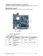
Страница 193: ...CHAPTER 5 Jumper and Connector Locations ...
Страница 200: ...5 8 Jumper and Connector Locations ...
Страница 201: ...CHAPTER 6 FRU List ...
Страница 202: ...6 2 Aspire 4560 4560G Exploded Diagram 6 4 Main Assembly 6 4 LCD Assembly 6 6 FRU List 6 7 ...
Страница 217: ...CHAPTER 7 Model Definition and Configuration ...
Страница 218: ...7 2 Aspire 4560 4560G 7 3 ...
Страница 325: ...CHAPTER 8 Test Compatible Components ...
Страница 326: ...8 2 Microsoft Windows 7 Environment Test 8 4 ...
Страница 332: ...8 8 Test Compatible Components ...
Страница 333: ...CHAPTER 9 Online Support Information ...
Страница 334: ...9 2 Online Support Information 9 3 ...
Страница 336: ...9 4 Online Support Information ...


