sync on G or Y. The Component Video + Key module supports one
analog video input in any of the above formats (as well as wide band
RGB, which it can sample at the 4:4:4 rate), plus one analog key input,
both sampled at 10-bit resolution, plus a composite sync input if needed.
The Composite Video + Key module supports one composite analog
video (NTSC or PAL, depending on the line standard selected) input
and one analog key (monochrome only) input.
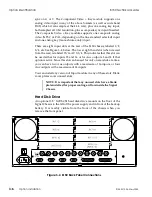
There are eight input slots at the rear of the 8150 chassis, labeled 1/2,
3/4, etc. See Figure 3-4, below. The lower right hand slot (when viewed
from the rear) is labeled 15/16 AUX 3/4. This indicates that this slot can
be used either for inputs 15 and 16 or for Aux outputs 3 and 4 if that
option
is active. Since this slot can be used for only one module at a time,
you can have two Aux outputs with a maximum of 16 inputs, or four
Aux outputs with a maximum of 14 inputs.
You can install any version of Input module in any of these slots. Blank
cover plates cover unused slots.
NOTE: It is important that any unused slots have a blank
plate installed for proper cooling air flow inside the Signal
Chassis.
Hard Disk Drive
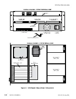
An optional 3.5" 1GB SCSI hard disk drive mounts on the floor of the
Signal Chassis to the left of the power supply and in front of the backup
battery. It is readily visible from the front of the chassis when you
remove the front panel.
Figure 3-4 8150 Back Panel Connections
Option Identification
8150 Technical Guide
3-6
Option Installation
9100-0212-04 - May 2000
Содержание ASWR8150
Страница 12: ...Table of Contents 8150 Technical Guide X Contents 9100 0212 04 May 2000...
Страница 39: ......
Страница 80: ...Control Panel Connector Detail 8150 Technical Guide 2 40 Installation 9100 0212 04 May 2000...
Страница 109: ...Option Installation 8150 Technical Guide 3 30 Option Installation 9100 0212 04 May 2000...
Страница 236: ...8150 Partial Parts List 8150 Technical Guide A 6 Appendix 9100 0212 04 May 2000...

