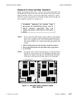
NOTE: The SCSI update involves inverting the voltage
regulator and changing two surface-mount resistors. If you
do not feel comfortable making these modifications
yourself, contact Accom Customer Service to arrange an
exchange or on-site service call.
STEP 4
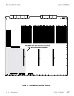
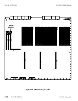
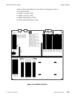
Connect the 4-way power harness to Motherboard connector
J35 (directly behind the backup battery) and bring the other
end of the cable to the front of the chassis.
STEP 5:
Connect the 50-way SCSI ribbon cable to Motherboard
connector J19 (above J35) and bring the other end of the cable
to the front of the chassis.
STEP 6:
Place the hard disk drive in the chassis on top of the ribbon
cable. Pull the ribbon cable forward to draw any slack to the
front of the disk drive. Place the disk drive circuit board side
down, with the 50-way and 4-way connectors facing toward
the front. Route the disk drive power harness under the main
DC power harness and down the right-hand side of the disk
drive.
STEP 7:
Connect the ribbon cable and power harness to the disk drive.
STEP 8:
Secure the disk drive from under the chassis with four 6-32 x
5/16" screws and #6 star washers.
STEP 9:
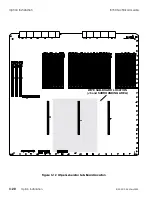
Install the shorting jumper on the Switcher board at location
JP3.
STEP 10:
Reinstall the Switcher board in the chassis and power up the
unit.
NOTE: It takes approximately ten seconds for the hard
drive to spin up to operating speed after a power cycle. This
creates a short delay in accessing the Disk menu for the
first time after a power cycle.
Option Installation
8150 Technical Guide
3-28
Option Installation
9100-0212-04 - May 2000
Содержание ASWR8150
Страница 12: ...Table of Contents 8150 Technical Guide X Contents 9100 0212 04 May 2000...
Страница 39: ......
Страница 80: ...Control Panel Connector Detail 8150 Technical Guide 2 40 Installation 9100 0212 04 May 2000...
Страница 109: ...Option Installation 8150 Technical Guide 3 30 Option Installation 9100 0212 04 May 2000...
Страница 236: ...8150 Partial Parts List 8150 Technical Guide A 6 Appendix 9100 0212 04 May 2000...

