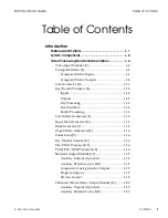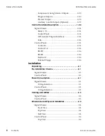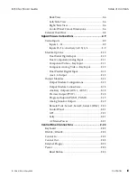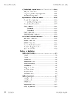
Back View ....................................................................2-6
Left/Side View ...........................................................2-6
Right/Side View.........................................................2-6
Control Panel Cutout Dimensions...........................2-6
External Disk Drive ..........................................................2-8
Signal Chassis Connections ........................................ 2-9
Video Inputs ......................................................................2-9
Inputs 1 - 14 .................................................................2-9
Inputs 15/16 - Auxiliary (AUX) 3/4 .......................2-9
Module Options ..............................................................2-10
Dual Serial Digital Input .........................................2-10
Dual Component Analog Input .............................2-11
Component Video + Key Input..............................2-11
Composite Analog Video + Key Input .................2-12
Dual Parallel Digital Input......................................2-12
Aux 3, 4 Output ........................................................2-12
Output Modules..............................................................2-13
Output Module Configurations.............................2-13
Output Module Connections .................................2-18
Auxiliary Outputs (AUX 1, AUX 2) ......................2-18
Preview Output (PVW) ...........................................2-18
Program Outputs (PGM 1, PGM 2) .......................2-19
Analog Monitor Output ..........................................2-19
Remote Ports: Serial 1, Serial 2, Serial 3 (LINC) .2-20
Control Panel ............................................................2-21
GPI ..............................................................................2-21
Tally ............................................................................2-21
AC Mains Power ......................................................2-21
Control Panel Connections ...................................... 2-22
Keyboard ..........................................................................2-22
RS-232 / RS-422...............................................................2-22
Control In .........................................................................2-22
Control Out ......................................................................2-22
External Floppy ...............................................................2-23
Power ................................................................................2-23
Reset Button ..............................................................2-23
8150 Technical Guide
Table of Contents
9100-0212-04 - May 2000
Contents
III
Содержание ASWR8150
Страница 12: ...Table of Contents 8150 Technical Guide X Contents 9100 0212 04 May 2000...
Страница 39: ......
Страница 80: ...Control Panel Connector Detail 8150 Technical Guide 2 40 Installation 9100 0212 04 May 2000...
Страница 109: ...Option Installation 8150 Technical Guide 3 30 Option Installation 9100 0212 04 May 2000...
Страница 236: ...8150 Partial Parts List 8150 Technical Guide A 6 Appendix 9100 0212 04 May 2000...


