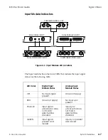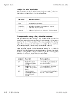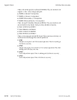
Output Module Indicators
The standard and optional Frame Delay Output modules each have a
dual color LED that indicates the reference status.
LED Color
Reference Status
RED
No reference present
YELLOW
Reference present but does not match
selected line standard
GREEN
Reference present at selected line standard
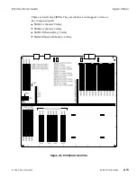
Component Key Module Jumpers
The optional Component Key Input module supports one
dedicated component video input and one dedicated key input. Sync is
expected on the Y/G component of the video signal, and on the key
signal. However, if you need to input a video signal that does not have
sync, the module has a separate sync input for this purpose.
There are three jumpers on this module for selecting of Y/G sync or
separate sync, for terminating or unterminating the separate sync signal,
and for selecting the level of sync on the key signal. The following table
describes the functions and settings for each jumper.
Jumper
Function
Pin Connections
JP1
Selects level of
the sync on key
input
1-2 = 300mV sync (default)
2-3 = 2V/4V sync
JP2
Selects sync on
video or separate
sync
1-2 = video sync (default)
2-3 = separate sync
JP3
Terminates or
unterminates the
separate sync
input
1-2 = 75-ohm term (default)
2-3 = hi-z termination
Signal Chassis
8150 Technical Guide
4-8
System Overview
9100-0212-04 - May 2000
Содержание ASWR8150
Страница 12: ...Table of Contents 8150 Technical Guide X Contents 9100 0212 04 May 2000...
Страница 39: ......
Страница 80: ...Control Panel Connector Detail 8150 Technical Guide 2 40 Installation 9100 0212 04 May 2000...
Страница 109: ...Option Installation 8150 Technical Guide 3 30 Option Installation 9100 0212 04 May 2000...
Страница 236: ...8150 Partial Parts List 8150 Technical Guide A 6 Appendix 9100 0212 04 May 2000...

