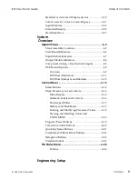
Component Analog Monitor Outputs ..................1-20
Program Outputs......................................................1-20
Preview Output ........................................................1-20
Auxiliary 3 and 4 Outputs (Optional)...................1-22
Control Functional Description ................................. 1-24
Signal Chassis ..................................................................1-24
Serial 1, 2, 3 ................................................................1-24
Control Panel ............................................................1-24
GPI (General Purpose Interface) ............................1-24
Tally ............................................................................1-24
Control Panel ...................................................................1-24
Control In...................................................................1-24
Control Out ...............................................................1-24
RS-232.........................................................................1-26
RS-422.........................................................................1-26
Keyboard ...................................................................1-26
External Floppy ........................................................1-26
Installation
Unpacking..................................................................... 2-1
Pre-Installation Checks................................................ 2-1
Signal Chassis ....................................................................2-1
Control Panel .....................................................................2-1
Power Consumption..................................................... 2-1
Signal Chassis ....................................................................2-1
Voltage Selection ........................................................2-1
Control Panel .....................................................................2-2
Voltage Selection ........................................................2-2
Cooling and Airflow ..................................................... 2-3
Signal Chassis ....................................................................2-3
Control Panel .....................................................................2-3
Dimensions and Physical Installation ......................... 2-4
Signal Chassis ....................................................................2-4
Front View ...................................................................2-4
Top View......................................................................2-4
Side View .....................................................................2-4
Control Panel .....................................................................2-6
Top View......................................................................2-6
Table of Contents
8150 Technical Guide
II
Contents
9100-0212-04 - May 2000
Содержание ASWR8150
Страница 12: ...Table of Contents 8150 Technical Guide X Contents 9100 0212 04 May 2000...
Страница 39: ......
Страница 80: ...Control Panel Connector Detail 8150 Technical Guide 2 40 Installation 9100 0212 04 May 2000...
Страница 109: ...Option Installation 8150 Technical Guide 3 30 Option Installation 9100 0212 04 May 2000...
Страница 236: ...8150 Partial Parts List 8150 Technical Guide A 6 Appendix 9100 0212 04 May 2000...


