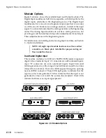
Dual Component Analog Input
This optional module supports several component analog formats,
including SMPTE/EBU N10, Betacam
®
, MII
®
, RGB, and monochrome
key signals. Input "A" connectors are odd numbered inputs, input "B"
are even number inputs. Input horizontal retiming is automatic, with a
range of one half line advanced to two lines delayed from reference.
Input analog-to-digital conversion is eight bits per channel. You can set
the input format type (RGB, several versions of Y/R-Y/B-Y, or key) in
the Engineering menu. The Analog Input modules have dual color LEDs
that light green to indicate that the input is present and genlocked.
Yellow indicates that the input is present but not genlocked or does not
match the system line standard. Red indicates that there is no sync
present on the Y/G channel, or that there is no input present at all.
The Dual Analog Component Input module requires sync on the Y or G
channel for proper operation. If you have sources that do not have sync
on the Y or G component, you must connect the signal that does not have
sync to the even numbered "B" input (2, 4, 6, etc.) and connect a cotimed
signal with sync (for example, key or separate sync) to the odd numbered
"A" input (1, 3, 5, etc.). See Section 5 – Engineering for more information.
Component Video + Key Input
This optional module provides one component analog video input and
one analog key input. The video input can be one of several component
analog formats, including SMPTE/EBU N10, Betacam, MII, and wide
band RGB. The key input supports only monochrome key signals. Input
horizontal retiming is automatic, with a range of one half line advanced
to two lines delayed from reference. Input analog-to-digital conversion
is ten bits per channel, with the ability to convert wide band video from
high resolution graphics or telecine at the 4:4:4 sampling rate, for use
with the 4:4:4 Chroma Keyer option.
You can set the input format type (RGB or several versions of
Y/R-Y/B-Y, sampled at either the standard 4:2:2 rate or at the high
resolution 4:4:4 rate) in the Engineering menu. If you select 4:4:4
sampling by using this input as a source for a 4:4:4 chroma key, the video
is filtered for wide band response and converted to a 4:4:4 signal. This,
however, occupies both the video path and the path normally used by
the key signal, so you cannot use the key input in this mode.
This module accepts sync on the Y/G and key inputs or a separate sync
input. If neither the video Y/G input nor the key input has sync, you can
supply separate sync, setting the jumper to apply this sync to the video
input. You must then use the Engineering menu Master/Slave setting
to lock the key input. See Section 5 – Engineering for more information.
8150 Technical Guide
Signal Chassis Connections
9100-0212-04 - May 2000
Installation
2-11
Содержание ASWR8150
Страница 12: ...Table of Contents 8150 Technical Guide X Contents 9100 0212 04 May 2000...
Страница 39: ......
Страница 80: ...Control Panel Connector Detail 8150 Technical Guide 2 40 Installation 9100 0212 04 May 2000...
Страница 109: ...Option Installation 8150 Technical Guide 3 30 Option Installation 9100 0212 04 May 2000...
Страница 236: ...8150 Partial Parts List 8150 Technical Guide A 6 Appendix 9100 0212 04 May 2000...

