background image


PROBOIL.2X user & installation guide v1e-2 

32 


2.2.4


Install the boiler 


The boiler should be the last section of the product to install, you should already have the tap and filter installed 

and the cold filtered (1/4” blue tube) water and hot water hose connector to the tap free and ready to connect. 


 WARNING

 You must not solely use the overall assembly diagram as a guide to installation, we are not liable for 

any safety or performance issues as a result of not following the step by step installation guide in this guide with due 
care. 


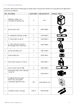
Key  Description 

Drawing 

PROBOIL.2X boiler unit 


½” male boiler inlet (with 

internal check valve) 

3/8” male boiler outlet 

mains power cable 

¼” flexible blue inlet pipe 

¼” x ¼” inlet pushfit 

connector  

½” blue Inlet “wingnut” 

connector (with integral 

“flat” rubber seal) 

inlet connector meshed 

filter seal 

Outlet connector rubber 

seal 

3/8” red Outlet “wingnut” 

connector 

Silicone outlet tube (0.75M) 

8mm barbed stem x 3/8” 

male tap connector 

2 x Wall fixing screws 

2 x Wall fixing plugs 

½” inlet transport cap 

3/8” outlet transport cap 

3/8” female flexible 

(braided/silicone) hose tap 

connector assembly and 

fibre seal (supplied with 

tap) 


Содержание PROBOIL.2X

Страница 1: ...Please read these instructions carefully before installation or use and retain for future reference You must install the tap and filter before the boiler We have a policy of continued product and qua...

Страница 2: ...NK 18 1 3 TROUBLESHOOTING 21 1 3 1 BOILER SCREEN AND INTERFACE 21 1 3 2 WATER TEMPERATURE 21 1 3 3 WATER DRIPPING FROM THE SPOUT END WHEN THE HANDLE IS IN THE OFF POSITION 22 1 3 4 WATER FLOW RATE STR...

Страница 3: ...must be carried out by authorised persons having knowledge and practical experience of the appliance in particular as far as safety and hygiene are concerned The PROBOIL system contains no user servic...

Страница 4: ...e event of any suspected problem you should immediately cease usage isolate the water supply disconnect the power and contact the service agent noted on the top of the boiler WARNING This appliance mu...

Страница 5: ...ct to your system and accordingly will invalidate your warranty If you have specific or unusual incoming water conditions please contact the service number on the boiler for further advice This applia...

Страница 6: ...n is reached Fig 2 and the maximum flow is achieved It is normal for the hot water to take a moment to dispense as the water may empty from the product after use 3 After use ensure to close the 98 wat...

Страница 7: ...rther 10 minutes 5 Dispense the entire contents of the boiler as normal until the heated water stream is entirely cold then allow it to continue to run for 5 minutes 6 Turn on the standard cold tap an...

Страница 8: ...The water inside the boiler tank will not exceed 98 to ensure compliance to local safety laws Standby Touch sensitive key switches the unit between on and standby modes press and hold for 1 5 seconds...

Страница 9: ...life is exceeded the product will beep daily to serve as an audible reminder We also operate a free reminder service when you register online In the event that power is interrupted to the boiler the f...

Страница 10: ...large bowl or pan or jug or small bucket A cloth A permanent pen 1 Remove the new filter from its packaging and remove any end dust caps plugs from both ends of the filter 2 Write todays date on the...

Страница 11: ...pipe from both ends of the filter cartridge To do this you should push the collet see drawing towards the centre of the filter whilst simultaneously pulling the blue flexible pipe in the opposite dire...

Страница 12: ...on fig 1 c Once the Tee valve is open air within the filter will purge spitting is normal at first and the water will start to flow from the filter exit d Run the water into the bowl until it runs cle...

Страница 13: ...er to around 2 litres per minute This can be checked with a timer and kitchen measuring jug c Once adjusted turn off the cold filtered water tap handle Fig 3 17 Turn the 98 C water handle fully on not...

Страница 14: ...tion 1 Press and hold the key for 1 5 seconds to activate this will turn the boiler into standby mode 2 Unscrew and remove the aerator housing 1 anti clockwise use rubber gloves if you need to get a b...

Страница 15: ...with plenty of water and seek medical advice After contact with skin wash immediately with plenty of water If swallowed seek medical advice immediately and show this container or label Descaler Ingre...

Страница 16: ...similar to remove it 9 Whilst taking care lift the PROBOIL 2X A unit out from the cabinet and place it on the countertop 10 Each bottle of PROBOIL descaling solution contains 200ml of descaling solut...

Страница 17: ...r than a further 30 minutes maximum for the descaler liquid to work It is normal for an odour to be present during this time 21 Remove the aerator from the end of the spout see previous section for de...

Страница 18: ...C tap handle on fully run for at least 3 litres or until the stream runs fully cold 3 Pull the mains power plug out from the socket on the left hand face of the boiler 4 Unscrew and detach the blue in...

Страница 19: ...found in the boiler inlet B whilst the boiler is upside down 11 Use only a non aggressive infant sterilising solution for example Milton concentrate Always read the label regarding the dilution The to...

Страница 20: ...s normal for an odour to be present during this time 18 Turn the boiler back into standby mode 19 Turn on the 98 C tap handle on fully keep the handle on for a minimum of 5 minutes 20 Turn the boiler...

Страница 21: ...use only contact service number on top of unit 1 3 2 Water temperature Issue description Possible issue solutions Water temperature is lower or higher than expected Press the keys and check the targe...

Страница 22: ...water only to confirm the incoming pressure Water is dripping intermittently from the centre or outer channel of the spout end aerator typically shortly after each use This is water retained within th...

Страница 23: ...onnecting the inlet adaptor G do not overtighten The boiler could be leaking from between the outlet adaptor and the boiler outlet Remove the outlet adaptor J and check that flat rubber seal I is pres...

Страница 24: ...rms The manufacturer may where appropriate provide replacement parts for your product or repair or replace all or part of your product at their discretion under this warranty Any associated or ancilla...

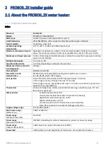
Страница 25: ...304 Selectable in tank temperatures 98 Maximum with adjustable heating point adjustment on screen 75 85 90 95 96 97 98 C range Heat up time From 20 C full and cold tank to 98 C displayed in Apx 9 minu...

Страница 26: ...2L Min Filter life Once installed recommended replacement schedule is 6 Months or use of capacity whichever is sooner filter life varies by location and usage pattern The filter life indicator bar and...

Страница 27: ...D ASPT1180 D1 1 flexible blue inlet pipe 1 5M E ASPT1180 E1 1 Inlet pushfit connector F ASPT1180 F1 1 Inlet wingnut connector With integral flat rubber seal G ASPT1180 G1 1 Inlet meshed filter seal H...

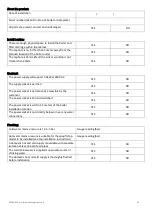
Страница 28: ...roduct will be a problem do not progress the installation without rectifying it first 5 Check the tap hole is no further than 1 meter away from the planned location of the boiler outlet 6 Check the co...

Страница 29: ...ly socket is earthed YES NO The power socket is permanently accessible by the customer YES NO The power socket is 13A and switched YES NO The power socket is within 1 4 meters of the boiler installati...

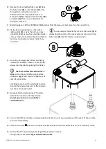
Страница 30: ...without a filtered cold water dispense option you should have 2 hoses without any connection a A outlet hose ending with a pushfit connection this will be the cold water output to the filter cartridge...

Страница 31: ...d exchange it avoid the rear of the cabinet if possible Always write the installation date on the filter label in permanent pen and leave the label on view it will help your customer as a visual remin...

Страница 32: ...ep installation guide in this guide with due care Key Description Drawing A PROBOIL 2X boiler unit B male boiler inlet with internal check valve C 3 8 male boiler outlet D mains power cable E flexible...

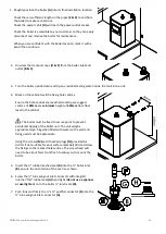
Страница 33: ...e level horizontally we suggest centres of 90mm at a minimum height of 245mm from floor level in the cabinet The boiler must be fixed to secure point to prevent accidental tipping of the boiler unit T...

Страница 34: ...desired minimum pipe length with a permanent pen We recommend cutting the blue flexible pipe E at least 200mm longer than the required minimum pipe length to allow the boiler to be serviced more easil...

Страница 35: ...cissors or similar 17 Firmly and fully push the silicone outlet tube K onto the red 3 8 x 8mm boiler outlet connector J Ensure the red 3 8 x 8mm boiler outlet connector J stem is clean of dirt or grea...

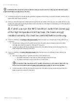
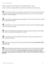
Страница 36: ...a fully cold state it is normal that the tap may drip slightly from the spout centre channel during heating this will self adjust with use 5 After the boiler reaches its READY state repeat steps 1 2 6...

Отзывы: