Section 1
Section 2
A1A2_DC(BS)
B1B2_DC(BS)
DB_BUS DB_BUS
DB_BUS DB_BUS
(WA1)A1
(WA2)B1
B2
A2
en04000498.vsd
IEC04000498 V1 EN-US
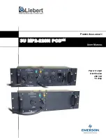
Figure 106:
Busbars divided by bus-section disconnectors (circuit breakers)
To derive the signals:
Signal
S1DC_OP
All disconnectors on bus-section 1 are open.
S2DC_OP
All disconnectors on bus-section 2 are open.
VPS1_DC
The switch status of all disconnectors on bus-section 1 is valid.
VPS2_DC
The switch status of all disconnectors on bus-section 2 is valid.
EXDU_BB
No transmission error from double-breaker bay (DB) that contains the above
information.
These signals from each double-breaker bay (DB_BUS) are needed:
Signal
QB1OPTR
QB1 is open.
QB2OPTR
QB2 is open.
VPQB1TR
The switch status of QB1 is valid.
VPQB2TR
The switch status of QB2 is valid.
EXDU_DB
No transmission error from the bay that contains the above information.
The logic is identical to the double busbar configuration “Signals in single breaker
arrangement”.
For a bus-section disconnector, these conditions from the A1 busbar section are
valid:
Section 12
1MRK 506 375-UEN A
Control
276
Railway application RER670 2.2 IEC
Application manual
Содержание RELION RER670
Страница 1: ...RELION 670 SERIES Railway application RER670 Version 2 2 IEC Application manual ...
Страница 2: ......
Страница 22: ...16 ...
Страница 48: ...42 ...
Страница 70: ...64 ...
Страница 80: ...74 ...
Страница 100: ...94 ...
Страница 210: ...204 ...
Страница 364: ...358 ...
Страница 384: ...378 ...
Страница 468: ...462 ...
Страница 494: ...488 ...
Страница 504: ...498 ...
Страница 505: ...499 ...