116
| NG C820 0 AN D PGC1000 US ER MAN UA L | 210 1510MNAH
For more information on enabling the diagnostics in PCCU, click
Diagnostics
and then
Help
.
10.19 Replace the feed-through assembly
This section presents the procedures for the removal and installation of the feed-through assembly.
This assembly is located on the side of the analyzer. Read through all the procedural steps before
removing the assembly.
Before beginning the procedure, verify that the module is appropriately rated for the system voltage.
Compare the module voltage to the ID tag located on the side of the enclosure.
To replace the feed-through assembly:
1.
On the Analyzer Operation screen, click
Hold
under Next Mode. When the device completes the
current cycle and enters hold, continue to the next step.
2.
Collect data from the device.
3.
Back up the configuration files following the instructions detailed in section
.
4.
Using the
instructions, verify the battery status is ok before proceeding.
5.
Turn off all sample streams, calibration gas and carrier gas.
6.
Disconnect or remove the power from the device externally, or remove the J1 connector from
the termination panel.
7.
Gain access to the digital controller assembly by loosening the countersunk hex socket locking
set screw in the front end cap using a 1/16” hex wrench, then unscrewing the end cap.
8.
Following the instructions detailed in section
, remove the digital controller assembly. If
weather and circumstances permit, the digital controller assembly may be suspended by the
cables to eliminate stress on the cable connections. If this is the case, move to step 10.
9.
Carefully unplug the cable to the termination panel, leaving the lithium battery plugged in. Set
the digital controller assembly aside on a clean, lint-free surface.
10. Using a 5/16” hex wrench, loosen the mounting screw holding the analytical module in place
until the module can be slowly lifted from the enclosure, taking care to not pull the wires
attached to the rear of the assembly.
11. Detach the analytical module rear face jack J1 and J4 if the auxiliary heater is installed.
12. Set the module on a clean, lint-free surface.
13. Using a ¼” open end wrench, loosen the nut and remove the input line. Repeat for all the
sample, carrier and calibration gas lines.
14. Using a 5/64” hex wrench, loosen the feed-through set screw.
15. Unscrew the feed-through assembly, turning by hand counterclockwise until free.
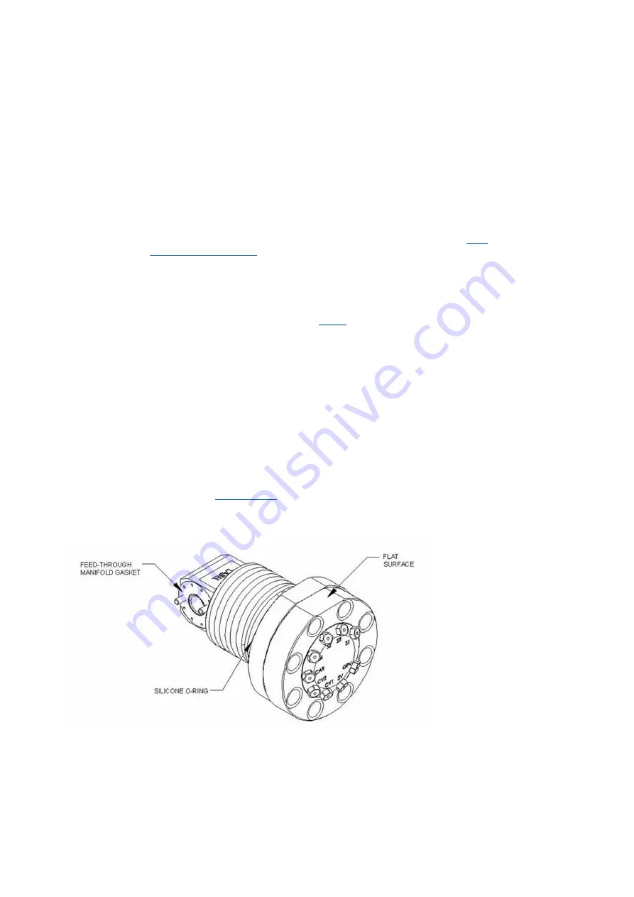
16. On the replacement assembly, install the O-ring and manifold gasket supplied with new feed-
through assembly (see
).
17. Carefully apply the sealing thread lubricant to the threads on the feed-through assembly, being
extremely careful to not contaminate the feed-through manifold and gasket.
Figure 10-18: Feed-through assembly
18. Insert the replacement feed-through assembly through the opening and screw in clockwise until
completely screwed in but not tight.
a.
If the flat surface, when screwed all the way in, is over 180 degrees past the top, reverse
the Feed-Through Assembly counter-clockwise until the flat surface is on top and horizontal.
b.
If the flat surface, when screwed all the way in, is less than 180 degrees past the top, turn
the assembly counterclockwise 1 full turn plus enough to bring the flat surface to where it is
on top and horizontal.


