background image

110

  | NG C820 0 AN D PGC1000 US ER  MAN UA L |  210 1510MNAH

10.15 Replace the digital controller complete assembly

Access to the digital controller assembly is gained by removing the front-mounted digital controller

assembly from the analytical module.
To replace the digital controller assembly:

1.

On the Analyzer Operation screen, click

Hold

 under Next Mode. When the device completes the

current cycle and enters hold, continue to the next step.

2.

Collect data from the device.

3.

Back up the configuration files, following the instructions detailed previously in the section,

10.6.

4.

Turn off all sample streams, calibration gas and carrier gas.

5.

Disconnect or remove the power from the device externally, or remove the J1 connector from

the termination panel.

6.

Following the instructions detailed in section

10.14

, remove the assembly.

7.

Unplug the termination panel to digital controller assembly flat ribbon cable, leaving the lithium

battery connected.

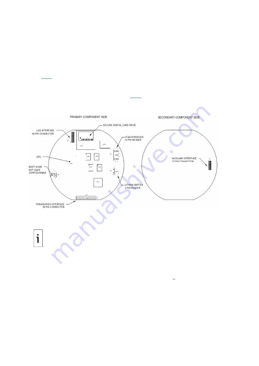
Figure 10-13: Digital controller board

8.

To reassemble using the replacement assembly, perform steps 6–7 in reverse order, being

careful to align the display screen before tightening. Check the lithium battery plug for proper

installation on the connector.

IMPORTANT NOTE: 

Note that the termination panel to digital controller ribbon cable pin 1 wire is 

not red. On the digital controller board, the red edge (pin 1) of the cable should plug onto pin 50, 
the right side of plug. The plug is keyed; do not force the plug into the connector.

9.

Re-plug the ground cable onto the new assembly.

10. Once assembled, apply power to the analyzer.

11. Adjust the contrast potentiometer R18 for optimum display. To adjust the display contrast, use

an extra small Phillips point screwdriver to turn the potentiometer R18 clockwise for more

contrast or counterclockwise for less contrast.

12. Restore the configuration files following the instructions in section

0

.

13. Reinstall front and rear end caps.

Since power was removed from the device, the analyzer will perform startup diagnostics and stabilize.

If the startup diagnostics were disabled, re-enabled and power cycle to the device. If the power has

been withheld from the device for an unknown or lengthy period of time, a complete startup should be

performed.
For more information on enabling the diagnostics in PCCU, click

Diagnostics

 and then

Help

.

Содержание NGC8200

Страница 1: ... ABB MEASUREMENT ANALYTICS 2101510MNAH Gas Chromatograph User Manual NGC8200 PGC1000 Measurement made easy ...

Страница 2: ...3 Feed through assembly 16 2 3 1 Configurations 16 2 3 2 Inlets 16 2 3 3 Vents 16 2 4 Analytical module 16 2 4 1 GC module 17 2 4 2 Analytical processor manifold assembly 17 2 5 Digital controller assembly with VGA display 18 2 6 Termination board 21 2 7 Local communication options 22 3 Embedded software and user interface 22 3 1 Embedded software 22 3 2 User interface PCCU32 22 3 3 Audit quality ...

Страница 3: ...nections 39 4 6 Vent lines connections 40 4 7 Security seal 41 5 Wiring 42 5 1 Wire for serial communication 42 5 2 Wire for power and grounding 42 5 2 1 Power supply requirements 43 5 2 2 Operating voltages and cable lengths 43 5 2 3 Other considerations 44 5 2 4 Ground the analyzer 44 5 2 5 Cathodic protection 44 5 2 6 Wire the analyzer power connector 44 6 Startup 45 6 1 Download PCCU32 from th...

Страница 4: ...rol file 91 9 2 3 Create the administrator account 91 9 2 4 Create additional user accounts with standard roles 93 9 2 5 Save RBAC configuration file 94 9 3 Save security configuration on the device 95 10Maintenance 97 10 1 Maintaining cleanliness 97 10 2 Visual inspection 97 10 3 Technical support and returns 98 10 4 Spare part components 98 10 4 1 Replacement components 98 10 4 2 Replacement par...

Страница 5: ...ssor Control Test 124 11 1 4 Stream Test 124 11 2 Troubleshooting Alarms 125 11 2 1 Alarm definitions 126 11 2 2 Pressure Regulator 1 or 2 Alarm 126 11 2 3 Sample Pressure Alarm 127 11 2 4 Oven Temperature Error Alarm 127 11 2 5 No Stream Valve Selected 127 11 2 6 Digital Analog Board Communication Error Alarm 128 11 2 7 Calculation Error Alarm 128 11 2 8 Calibration Un normalized Error Alarm 128 ...

Страница 6: ...2 VDC battery power supply system maximum cable lengths 44 Table 6 1 Cable for USB connection 49 Table 6 2 Required cables for connection with MMI port 51 Table 6 3 Ethernet cabling for local connection 53 Table 6 4 Station setup basic parameters 59 Table 6 5 Stream setup screens 60 Table 6 6 Peak find troubleshooting 73 Table 6 7 Suggested carrier pressure setpoint adjustment values 74 Table 8 1 ...

Страница 7: ... 2101429 INMETRO Control Drawing NGC PGC Ex d 2106190 Other documentation Technical bulletin Upgrading NGCs TekBul 220 Modbus Registers for NGC8200 and PGC1000 2108309 Return Material Authorization RMA request form 2108308 Compliance Cyber security This product is designed to be connected and communicate information and data via a network interface All ABB products should be connected to a secure ...

Страница 8: ... on health and the environment These steps ensure compliance with the Waste Electrical and Electronic Equipment WEEE Directive Waste electrical and electronic equipment WEEE shall be treated separately using the national collection framework available to customers for the return recycling and treatment of WEEE Safety Read these instructions carefully before installation and commissioning These ins...

Страница 9: ...an install wire verify the power on sequence and configure Do not open the equipment to perform any adjustments measurements maintenance parts replacement or repairs until all external power supplies have been disconnected When opening covers or removing parts exercise extreme care as live parts or connections can be exposed Capacitors in the equipment can still be charged even after the device ha...

Страница 10: ...sis Tubing gas lines to deliver and vent gas to and from the analyzer Figure 1 1 shows the analyzer in a typical single stream pipeline installation This scenario includes a sample probe an optional sample conditioning module and carrier and calibration gas Lines for the entry of the gas sample carrier gas and calibration gas are installed into the analyzer s feedthrough inlets The sample probe ca...

Страница 11: ...none a factor of one is used Analysis results are stored in the analyzer Once a sample processing cycle is completed the sample is vented from the analyzer Analysis results can be collected directly from the analyzer using the operator interface PCCU or the analyzer can be configured to transmit results to other systems using any of the supported communication protocols 2 Hardware description Tabl...

Страница 12: ...4 inches 29 lbs Metric 241 3 mm 224 0 mm 397 3 mm 10 8 kg Notes 1 Usually experienced at startup Use this for power supply sizing requirements includes approx 20 buffer and is calculated for maximum allowable power supply voltages 2 At recommended AC power supply voltage Highly temperature dependent with feed through heater operating continuously Usually occurs at only the coldest ambient operatin...

Страница 13: ...d PGC1000 The end caps have precision engineered threading The enclosure and all fittings including feed through MMI connection and breather are tested to Nema Type 4X Unauthorized removal of the end caps is protected with a 1 16 hex socket set screw on each end cap Entries in the explosion proof enclosure constitute a flameproof joint Flameproof joints including threaded entries in the explosion ...

Страница 14: ...14 NGC8200 AND PGC1000 USER MANUAL 2101510MNAH 2 2 1 Exterior enclosure dimensions Figure 2 2 NGC8200 and PGC1000 enclosure face Figure 2 3 NGC8200 and PGC1000 enclosure left side ...

Страница 15: ...2101510MNAH NGC8200 AND PGC1000 USER MANUAL 15 Figure 2 4 NGC8200 and PGC1000 enclosure right side Figure 2 5 NGC8200 and PGC1000 enclosure underside ...

Страница 16: ...s to the analytical module Note that this cable comes in two configurations 12 VDC and 24 VDC 2 3 2 Inlets Feed through assembly inlets take in the stream gas samples and carrier gas They all have internal replaceable 0 5 micron filters The inlets are 4 process stream inputs S1 S2 S3 and S4 1 carrier gas input CAR NOTICE Equipment damage risk The 0 5 micron filters should not be considered a repla...

Страница 17: ...cal processor manifold assembly This assembly is equivalent to a complete analytical module without a GC module The manifold portion of the assembly is comprised of the manifold plate heater valves and various cables to other major components The manifold plate and heater maintain constant temperature for the GC module and columns The valves control the stream processing carrier and calibration ga...

Страница 18: ...sor is not running properly This is a field replaceable part Figure 2 9 Analytical processor manifold assembly 2 5 Digital controller assembly with VGA display The Digital Controller assembly Figure 2 10 contains the digital electronic board mounting assembly and a VGA display The digital controller provides control parameters to the analytical processor board and stores and processes the data sen...

Страница 19: ...he processes stop operation start operation and calibrate Navigate screens using the display magnet The VGA display features VGA display circuit board Two LED status indicators user programmable The default left LED flashing light indicates a fault alarm and a solid light indicates a warning alarm Right LED solid light indicates device is not in auto run mode User interface with hall effect magnet...

Страница 20: ...20 NGC8200 AND PGC1000 USER MANUAL 2101510MNAH Figure 2 11 NGC VGA display screen ...

Страница 21: ...plosion proof port USB host interface J5 or Optional RS 232 J7 Communications Ethernet interface J3 with 3 LED status indicators D11 D12 D13 2 serial ports RS 232 RS 422 RS 485 software selectable J8 and J10 Onboard security 1 Security Toggle Switch S2 1 Security Switch Status indicator LED D3 software programmable 1 status indicator LED software programmable D4 Reset button S1 The secondary compo...

Страница 22: ...rol RBAC admin defined user credentials Options for configuration access control reporting and data communications are available on the user interface PCCU 3 2 User interface PCCU32 PCCU32 is the host based user interface to the analyzer It runs in a Windows environment and offers options for access configuration control reporting and data communications It supports the following Communication to ...

Страница 23: ...ISO summation factor ISO mass JIS GPA summation factor NX 19 3 5 Calculation options During stream setup the user may select from several calculation files Selection of a suitable file automatically sets up other factors such as concentration Btu basis and saturated gas treatment For additional information refer to the PCCU help topics 3 6 Engineering units User selectable engineering units may be...

Страница 24: ...ee section 9 Configure security for details 4 Installation This chapter provides information for field installation of the analyzer After completing the procedures within this chapter the analyzer is ready for startup The following procedures unless otherwise stated are applicable to all analyzers The analyzer is designed to be pipe mounted see Figure 4 1 Optionally a shelf mounting kit see Figure...

Страница 25: ...rate carton Carefully remove all internal and external packing material Carefully remove all items from the box After removing the protective shipping cover from the analyzer compare shipped contents with those listed on the bill of lading All items should match those on bill of lading Examine internal components for evidence of damage Visually inspect exterior of device for dents chipped paint sc...

Страница 26: ... 2 inch pipe with flange kit Optional kit comes with flange screws washers and coupling To install the pipe saddle 1 Position the pipe saddle on the meter run Select a location that allows easy access and is close to the sample probe Lines should be as short as possible 2 Temporarily attach the saddle on the meter run pipe using the U bolt and associated hardware see Figure 4 3 3 Screw one end of ...

Страница 27: ... 6 Proceed to mount the analyzer see section 4 3 4 Figure 4 4 Shelf installation 4 3 4 Analyzer installation Once the mounting system has been installed regardless of the type used follow these instructions to install the analyzer onto the mounting pipe Before beginning review the procedure and the materials required for installation Materials Installed mounting pipe Four 5 16 inch hex socket scre...

Страница 28: ...nal mounting flange pipe small adjustments may be made to orientation Apply additional pressure to the mounting pipe with a pipe wrench and then tighten the mounting pipe into the shelf mounted flange or pipe saddle flange Otherwise loosen the hex socket set screw rotate the device and retighten 4 4 Sample system installation 4 4 1 Sample system design considerations Information in this section en...

Страница 29: ... to the chromatograph to be as short as possible The coupling should be mounted so that the probe can be installed horizontally or vertically on the meter run pipe This means the coupling should be mounted on either the top or the side of the meter run pipe The sample probe should not be mounted at the ends of headers dead T s large volume accumulators or other spots where gas is likely to be stag...

Страница 30: ...ample probe threads are free from dirt and debris 5 Using PTFE tape or pipe dope wrap or cover NPT threads of sample probe see Figure 4 8 Figure 4 8 Sample probe 6 Insert gas probe into pipeline coupling see Figure 4 9 7 Using the correct tool tighten the probe so there is no gas leakage Do not over tighten 8 Install the shut off valve on the outlet port of the sample probe if desired Figure 4 9 S...

Страница 31: ... liquid carry over would harm the chromatograph if it was introduced as a sample This model contains a liquid shut off to protect the GC The liquid shut off resets itself when liquids are no longer present Particulate coalescing filter Liquid vapor separator 2104677 001 Designed to remove condensing sample line liquid or water that has penetrated the sample probe The system expels the liquid or wa...

Страница 32: ...32 NGC8200 AND PGC1000 USER MANUAL 2101510MNAH Figure 4 11 Single and multiple stream sample conditioning assemblies Figure 4 12 Single stream conditioning module dimensions ...

Страница 33: ... 62 x 1 5 U bolt Two 5 16 inch SST split washers Two 5 16 inch SST flat washers Two 5 16 18 SST lock nuts Sample conditioning module s and hardware The two sample conditioning module mounting brackets are installed identically The single module bracket holds a single stream sample conditioning module while the multiple module bracket holds up to three sample conditioning modules Figure 4 14 Sample...

Страница 34: ...crew the nut onto the end of the bolt and finger tighten 6 Repeat steps 4 and 5 for the other side of the U bolt 7 Move the bracket into position underneath the analyzer being careful to allow clearance for the sample conditioning module s 8 Tighten both nuts 4 4 6 Sample line connections After the installation of the sample conditioning module s install the sample tubing from the sample probe to ...

Страница 35: ...sealing screw NOTICE Equipment damage Leave the sealing screw in any unused ports If unused stream ports are not sealed moisture can enter the manifold which can damage the instrument and void the warranty 12 Make the necessary bends in the tubing to ease installation of the tubing into the output fitting on the sample conditioning module and the stream input into the input on the feed through ass...

Страница 36: ... 300 Methane C1 89 570 Neo Pentane Neo C5 0 100 Carbon Dioxide CO2 1 000 Iso Pentane IC5 0 100 Ethane C2 5 000 Normal Pentane NC5 0 100 Propane C3 1 000 Hexanes and Heavier C6 0 030 Iso Butane IC4 0 300 4 5 2 Cylinder rack installation on meter run The carrier calibration gas cylinder rack is used to hold the carrier and calibration gas cylinders on installations not using an environmental enclosu...

Страница 37: ...egulations for classified hazardous atmospheres 4 Remove the J2 field wiring connector from the termination panel located inside the rear of the enclosure Figure 4 17 Carrier gas pressure regulator with relief valve 5 Using a small flat head screwdriver loosen DI1 pins 1 and 2 6 Insert the red wire into the terminal pin 1 7 Retighten pin 1 8 Insert the black wire into the terminal pin 2 9 Retighte...

Страница 38: ...ks DANGER Serious damage to health risk to life Do not connect the low pressure switch directly to the analyzer without a customer supplied intrinsically safe barrier It must meet all national regulations for classified hazardous atmospheres 5 Using a small flat head screwdriver loosen DI2 pins 3 and 4 6 Insert the red wire into the terminal pin 3 7 Retighten pin 3 8 Insert the black wire into the...

Страница 39: ...igure 4 21 2 Locate the inch low pressure output fitting on the installed pressure regulator 3 Measure and cut the 1 16 inch SST tubing to the required length 4 Make the necessary bends in the tubing to ease the installation of the tubing into the analyzer and pressure regulator Figure 4 21 Carrier and calibration gas connections IMPORTANT NOTE Tube ferrule and nut should always enter the connecti...

Страница 40: ...ort lines Follow the requirements of national and local codes during installation Materials Four 1 16 inch ferrules and nuts Four 1 16 inch SST vent tubing supplied with analyzer or Four 1 16 inch SST tubing amount to be determined by the technician based on the distance from the analyzer to the external vent location To connect vent lines 1 Locate the gauge port vent GPV sample vent SV column ven...

Страница 41: ...es located in the tab located on each end cap see Figure 4 23 Figure 4 23 End cap tabs for security seal Customer supplied materials 1 each security wire seal Seal press To attach a security seal 5 Insert security wire through holes located on end cap tabs 6 Bring ends together and insert through holes in security seal see Figure 4 24 7 Use seal press to compress seal into wire Ensure that the wir...

Страница 42: ...N SERIAL PORT 1 J8 SERIAL PORT 1 J8 SERIAL PORT 1 J8 1 Power Out Power Out Power Out 2 Ground Ground Ground 3 Switched Power Out Switched Power Out Switched Power Out 4 Operate Operate Operate 5 Not Used RRTS RTS 6 Request To Send Bus Transmit Bus 7 Transmit Data Bus Transmit Bus 8 Receive Data No Connection Receive Bus 9 Clear To Send CTS No Connection Receive Bus PIN SERIAL PORT 2 J10 SERIAL POR...

Страница 43: ...zer end The other end should be left to float left unconnected see Figure 5 1 5 2 2 Operating voltages and cable lengths The analyzer is designed for connection to a 12 VDC or 24 VDC power source The 12 volt power source must provide a minimum of 10 5 VDC to a maximum of 16 VDC at 4 amps minimum and the 24 volt must provide a minimum of 21 VDC to a maximum of 28 VDC at 2 2 amps The configurations ...

Страница 44: ...t etc For installations in an office environment ensure that a good earth ground to the analyzer is established Improper grounding can lead to erratic behavior If the device is not properly grounded the user could have as much as 60 VAC half line voltage on the case of the equipment due to capacitive coupling within the power supply Refer to the power supply manufacturer for specific grounding req...

Страница 45: ...and section 5 Wiring are completed DANGER Explosion Hazard Do not open or remove any enclosure covers unless the area is known to be non hazardous For additional or advanced configuration options click Help on the PCCU32 screens for the analyzer 6 1 Download PCCU32 from the ABB website The latest PCCU version is available on the ABB website This procedure describes how to locate and download the l...

Страница 46: ...1 ABB Upstream home page 3 On the PCCU page scroll down and select the Downloads tab Figure 6 2 Figure 6 2 PCCU page document downloads 4 On the PCCU Downloads page scroll down on the left menu of available documents locate and select Release note Figure 6 3 ...

Страница 47: ...n package file name has the part and rev number for example 2103445 098EX ZIP 10 Select Save at the download prompt Save the file on the laptop used to configure the device 6 2 Install PCCU32 PCCU32 software operates in a Windows environment PCCU32 must be installed in the PC or laptop that connects to the analyzer for configuration and operation This procedure assumes that the desired PCCU32 inst...

Страница 48: ... supports the use of any of these ports but must be configured for each type The following sections describe how to set up PCCU to connect with the analyzer for each port type Select the procedure for the preferred connection choice Connections to the external port may be required in certain locations for safety IMPORTANT NOTE If the Invalid Security Code warning appears when attempting to connect...

Страница 49: ...using the USB port 1 Connect the USB cable from the laptop to the analyzer The cable s client end type B connects to the analyzer The Host end type A connects to the laptop s USB port 2 Power on the analyzer Observe the analyzer s LCD initializing sequence Diagnostic tests begin immediately See section 6 4 Power on sequence for details 3 Launch PCCU Locate and select the PCCU shortcut The main PCC...

Страница 50: ... match the laptop s date and time which is usually the case with a new system When connection is successful the analyzer s startup wizard screen displays The wizard provides the sequence to complete basic analyzer configuration Go to section 6 5 Startup wizard 6 3 2 Connect using RS 232 port This section describes initial local connection using the analyzer s RS 232 port Use this port for local co...

Страница 51: ...382 001 May be available in several lengths The 8 cable is part number 2015240 004 To set up communication using the MMI port 1 For laptops with legacy COM1 COM2 interfaces connect the MMI cable as follows a Connect the circular miliary end to the MMI port on the analyzer b Connect the DB 9 end to the laptop s COM1 or COM2 port 2 For laptops with USB ports only use also the Digi Edgeport 1 convert...

Страница 52: ...complete basic analyzer configuration Go to section 6 5 Startup wizard 6 3 3 Connect using Ethernet port If the analyzer s Ethernet port is disabled in a new analyzer you can connect your laptop PC to the port and then power on the analyzer and have the Ethernet port temporarily enabled This happens also if you connect to the port and the analyzer is rebooted IMPORTANT NOTE For the Ethernet port t...

Страница 53: ...n Figure 6 14 shows the crossover cable pinouts If you build your own cable ensure the connectors are properly crimped and that no internal wires are exposed outside of the connector Test the cable for proper connectivity If you are experiencing connection issues always check that you have the correct cable pinout and that the cable and connectors are free from damage and are properly inserted in ...

Страница 54: ...0 11 To configure PCCU32 for TCP IP communication 1 Connect an Ethernet cross over cable between the PC and analyzer Make sure the PC or laptop is powered on 2 Power on the analyzer Diagnostic tests begin immediately See section 6 4 Power on sequence for details 3 Launch PCCU32 4 Click Setup on the PCCU32 toolbar menu Figure 6 16 PCCU32 Setup 5 On the System Setup tab under PCCU Connect Method cli...

Страница 55: ...time which is usually the case with a new system When connection is successful the analyzer s startup wizard screen displays The wizard provides the sequence to complete basic analyzer configuration Go to section 6 5 Startup wizard 6 4 Power on sequence 6 4 1 Initialization At power on the analyzer starts its initialization sequence Performs a cold start Loads startup information into RAM memory T...

Страница 56: ...nostics and has passed the appropriate tests with the exception of streams with no pressure the device will go into hold mode We recommend that the device be allowed to run for at least eight hours to completely stabilize Then perform calibration as described in section 7 6 4 2 1 Carrier pressure regulator tests This test compares the actual column pressure to the column pressure set point using c...

Страница 57: ...tream Pressure Initial 5 psi Resting 5 psi Maximum 20 psi Holding 2 psi for 6 seconds Flowing Between 5 and 20 psi Ending 5 psi Results from testing the various stream pressures at first time installation helps to verify that the Stream Sample Valves SSVs or the Sample Shut Off SSO valve are not leaking when closed It also verifies that the SSVs allow sample gas to pass through when opened IMPORTA...

Страница 58: ...y with the Diagnostics Follow the wizard to complete configuration even if the diagnostics are still running IMPORTANT NOTE As each wizard screen is displayed its associated help topic also displays Figure 6 22 If the topic is closed you can display it again by clicking Help on the desired screen Figure 6 22 Context sensitive Help topic ...

Страница 59: ...p screen are not required for startup For more information regarding the setup of these items click Help to see more information about each screen 5 When all desired changes have been made click Send and then Next to move to the next screen Table 6 4 Station setup basic parameters Description Value Station ID Assign unique identifier 10 alphanumeric digits Location Enter meter location 24 alphanum...

Страница 60: ...eam The Calibration tab displays see section 6 5 3 next IMPORTANT NOTE During the stream setup each time Next is selected you should see the Stream ID located on the first line of each screen Update values as required Move through all four streams even if the device is a single stream device Table 6 5 Stream setup screens Setup Tab Values Stream ID Assign unique identifier 10 alphanumeric digits L...

Страница 61: ...C7 14 285 C8 User Defined C6 Not Reported The selection will use what the user enters on the C6 split ratios Only the split values not the C6 value are transmitted if required C6 C7 C8 C9 C10 Used to enter split percentages if desired Note 1 File selection automatically sets the remainder of the items on this screen See PCCU Help files for more information Note 2 A selection in this field other th...

Страница 62: ...Total Mole equals 100 and all desired changes have been made click Send and Close 6 5 4 View diagnostics Diagnostics began when power was applied to the device You should not proceed beyond the Diagnostics screen until diagnostics have passed 1 Click the Diagnostics tab to verify that the analyzer has completed and passed the tests Figure 6 26 If any of the test fails correct the problem Figure 6 ...

Страница 63: ...mpletion of diagnostics select Stream Sequence from the Analyzer Operation screen It is recommended that the diagnostic stream test be performed on streams enabled after initial diagnostics Select Help for additional information 6 5 5 Update configuration Save the device configuration file following setup 1 At the Update Configuration tab click on the value field next to Save Configuration Data an...

Страница 64: ...blend If composition analysis does not reflect the expected composition in the blend the analyzer requires calibration Perform this procedure prior to running the process streams To run the analyzer s calibration stream 1 At the Analyzer Cal Stream tab select Stream 4 on the left side of the screen Figure 6 29 The on screen indicator next to Stream 4 should light up the cycle clock begins and you ...

Страница 65: ...r three cycles approximately 10 to 15 minutes During the final cycle change the next mode to Hold When the device completes the current cycle it will enter hold mode 3 Select Next to verify analysis results 4 At the Results tab compare normalized percent for each component to the component and percent listed on the calibration blend cylinder Component percentages should be the same ...

Страница 66: ...en chromatograms have been verified ensure that unused streams are disabled Streams that are used and have passed diagnostics are automatically enabled If you have already configured the streams as required go to step 10 next if not follow the procedure in section 6 5 7 Enable Disable streams 10 Next to begin the sample stream analysis and to place the analyzer in service 6 5 7 Enable Disable stre...

Страница 67: ...6 5 8 Run Analysis Process streams 6 5 8 Run Analysis Process streams 1 At the Analysis Process Streams tab select Run on the left side of the screen Figure 6 33 to begin the first sample stream in the sequence The indicator next to Run should turn blue the cycle clock begins and you should see on screen animation of gas flowing on the sample stream Figure 6 34 Figure 6 33 Run Analysis Sample Stre...

Страница 68: ...etermined that calibration is required it is recommended that the device be allowed to run for at least eight hours before calibration to allow the device to stabilize To complete the Startup Wizard 1 On the Complete tab click Close to exit the wizard Figure 6 35 Figure 6 35 Final Wizard screen After the wizard is closed the Operation screen displays Figure 6 36 For additional configuration or ope...

Страница 69: ...ted results IMPORTANT NOTE This section describes procedures using peak find in Manual mode This mode allows user configuration of relevant parameters if fine tuning correction is needed Manual mode is the only available mode and is automatically used in systems with versions of Flash 2102411 043 and OS 2102141 016 and later Earlier software versions show options for either Manual or Automatic mod...

Страница 70: ...Post Process after changes to view the effect of the changes Modifications to the Pressure and time duration parameters require the run of a cycle Click Run a Single Cycle to view the effect of the changes Figure 6 38 Peak Setup screen It is assumed that a PCCU32 connection with the analyzer is successfully established and the analyzer Operation screen is in view It is also assumed that a number o...

Страница 71: ...C6 heavy components Figure 6 40 chromatogram is shown by default The C2 N2 light components Figure 6 40 chromatogram is available in the other tab If no chromatogram displays a If the message to run a cycle displays click the Run Single Cycle button b Click Re read and wait for the chromatogram to display 5 In systems with older software select the Manual checkbox a Observe the displayed chromatog...

Страница 72: ...72 NGC8200 AND PGC1000 USER MANUAL 2101510MNAH Figure 6 40 Peak Find screen for C3 C6 chromatogram heavies Figure 6 41 Peak Find screen for N2 C2 chromatogram lights ...

Страница 73: ... Pressure Set Point may be too high or too low See section 6 6 1 1 Adjust Carrier Pressure Set Point Gate times may be incorrect See section 6 6 1 2 Adjust Peak Gate times IMPORTANT NOTE Modifications to parameters in the Peak Setup table are processed by the Post Process function without the need to run a cycle Click Post Process after changes to immediately view the effect of the changes Modific...

Страница 74: ...ted in the chromatogram 8 Repeat this process until you obtain preferred results 6 6 1 2 Adjust Peak Gate times Gate On and Gate Off times on the Peak Setup tab table determines when to start and stop looking for peaks Each Gate On Gate Off time applies the parameters in its row to the peaks in its time frame The Gate On time should begin in an area prior to the first component peak and in a relat...

Страница 75: ...the nC5 peak indicates that the Forward Flow is too long It may be necessary to shorten the Forward Flow Flow Inject Time Make small time increment changes to this parameter to avoid over compensation Adjust the Forward Flow Inject Time in the carrier pressure time parameter area 1 Select the desired chromatogram 2 Type a new value for the Forward Flow Flow Inject Time field 3 Click Send Setup 4 C...

Страница 76: ...tion Setup window appears 2 On the Setup tab set up the blend concentrations Figure 7 1 Set up gas concentrations 3 Click Send 4 From the Operation screen select Cal Figure 7 2 Run calibration 5 When the current cycle completes the device should begin a calibration on the designated calibration stream default is stream 4 ...

Страница 77: ...ters proceed to the Troubleshooting section 8 Carefully examine the calibration stream s Chromatogram 1 and Chromatogram 2 by clicking the button Look for unlabeled peaks and base line anomalies Use Figure 7 4 and Figure 7 5 as a guide If errors exist proceed to the Troubleshooting section 9 Once the device is running smoothly is producing good chromatograms and all the peaks are labeled and eluti...

Страница 78: ...C3 C6 heavy components and N2 C2 light components C3 C6 is displayed first If no chromatograms display click Re read Figure 7 6 C3 C6 heavies 2 Look at the date time below the chromatogram This time should coincide with the start of the last cycle of the calibration process that was just run This signifies that the calibration data was accepted no alarms etc If this displays an older date and time...

Страница 79: ...nt label Figure 7 7 N2 C2 lights 6 Place the vertical line of the cursor over the small tick mark on C2 and verify the time in the upper right corner of the chromatogram is approximately 220 seconds within 3 or 4 seconds 8 Configure for network connection The analyzer supports network communication though its Ethernet port If the analyzer will be connected to an Ethernet network enable and configu...

Страница 80: ...in field scenarios When using DHCP the IP address may change if the analyzer is power cycled If a static address is required keep DHCP disabled 8 3 Cabling for connection to network Use straight Ethernet through cables to connect the analyzer to network equipment Table 8 1 shows cable details Note that most network equipment can detect cable type and autoconfigure for that type straight through or...

Страница 81: ...on IMPORTANT NOTE Analyzer reboot is required to enable the Ethernet interface If the analyzer is already in RUN mode it will resume RUN mode after the reboot if the Process Mode After Start Up parameter on the Diagnostics tab is set to Previous Mode You can also perform Ethernet configuration changes through a connection using either the USB or MMI ports If using the USB establish a connection pe...

Страница 82: ...Figure 8 5 5 Ensure DHCP is set to No 6 Configure IP parameters Type IP address default gateway subnet mask Take note of the IP address It will be needed later to verify network communication 7 Set the Network Adapter to Enable Figure 8 5 Configuration for Network connection 8 Click Send The new IP parameters display ...

Страница 83: ...thernet configuration verify network connectivity If the configuration is correct you should be able to ping the analyzer s IP address and receive a response or be able to establish a connection using PCCU To verify connection over the network using PCCU 1 Connect the analyzer Ethernet port to the local network switch or router 2 Configure the laptop with valid IP address compatible with the IP ad...

Страница 84: ...ing DHCP ensure that the IP parameters display If they don t check that the DHCP server is enabled and connected to the network In field networks the DHCP server is typically embedded in the network router The network router should have the correct IP configuration be connected to the network and have its DHCP services enabled 4 Check Ethernet cables and connectors a Ensure all devices are connect...

Страница 85: ...ed 9 1 Configure bi level security This procedure enables security with the hardware security switch and the configuration of bi level security access for PCCU32 When analyzer security is configured in this way security codes are required for connection to the device with PCCU32 Table 9 2 describes the two levels of security for this method Each level requires the configuration of a security code ...

Страница 86: ...Security Switch Status is OFF Figure 9 2 Security switch status Off 6 Type a four digit security code into Security Code Level 1 Level 1 access grants read only access to the device 7 Type a four digit security code for Security Code Level 2 Level 2 access grants read and write access to the device IMPORTANT NOTE Record the security codes They are not visible on the Station Setup tab after you sav...

Страница 87: ... in effect 11 Click Close to close PCCU32 connection with device Figure 9 5 Security Switch Status On IMPORTANT NOTE PCCU32 requires the security codes the next time it attempts connection with the analyzer 12 Test security code enforcement Click the Setup icon on the PCCU top menu bar 13 Type the security code in the Level 1 2 Security Code field Figure 9 6 14 Click Close to exit setup 15 Click E...

Страница 88: ...ase Access Control RBAC Role Based Access Control RBAC is a feature within PCCU32 that allows an administrator to designate roles and control access levels to various applications and processes in the analyzer The system provides pre defined privileges for each role When defining RBAC for the analyzer consider all required user access to the system First create an administrator account and then ad...

Страница 89: ... role access in RBAC PCCU32 Security Editor Figure 9 8 shows the default Advanced role definitions Note that the Advanced role does not have full access for some functions Default access configuration for each function can be customized by changing the default setting as necessary ...

Страница 90: ...t visible on the PCCU32 navigation tree The Send button is also grayed out on applications with read only functionality NOTICE Security override After RBAC is implemented it overrides the switch enforced bi level security 9 2 1 Default access roles Default roles are automatically available in PCCU32 Administrator Expert Advanced Basic File Admin The Administrator role has the highest level access ...

Страница 91: ...r accounts and assign default roles 4 Create customized roles if necessary 5 Configure communication ports 6 Save the security file 9 2 3 Create the administrator account To create the administrator account 1 Launch PCCU32 and click Operate Security Role Based Access Control Role Administration on the top menu bar Figure 9 9 Configure RBAC from PCCU32 2 On the Security Editor window select the Dev...

Страница 92: ...r user a Click Add User b Type the user name into the Name field c Type the password into the Password field d Click OK The Users list shows the administrator name with Basic as the default role Assign the correct role in the next step Figure 9 11 Type user credentials 5 Click the Role drop down list next to the user and select Administrator ...

Страница 93: ...tandard roles This procedure creates new users and assigns non administrator roles to those users To add new users 1 Click Add User a Type the user name into the Name field b Type the password into the Password field c Click OK The Users list shows the new user with a default role Assign the correct role in the next step Figure 9 13 New user credentials ...

Страница 94: ...ed analyzer if the configuration is applicable Using the same configuration file for multiple analyzers saves configuration time To save on a local drive 1 Type a description of the security file into the Description field 2 Click Save As to save the new security control file 3 Type a password for the security file and click OK The Save Security File dialog displays 4 Navigate to the appropriate f...

Страница 95: ...he analyzer however the security file cannot be disabled or removed To revoke RBAC security remove the file you will need to reload a new analyzer configuration file To save the security configuration on the analyzer 1 Click the Entry icon to connect to the analyzer The Analyzer operator screen displays 2 Click Operate Security Role Base Access Control Role Administration The Security Editor windo...

Страница 96: ...7 Click Send to save the security file on the analyzer 8 Click OK at the warning Figure 9 20 Send Security File warning 9 Click Close to exit the Security Editor Connection with analyzer will be lost 10 Restart PCCU32 11 Click Entry to connect with the analyzer again 12 Type credentials at the login prompt Figure 9 21 and then click OK 13 Verify that connection is established ...

Страница 97: ...ion If contamination is found the system should be shut down and cleaned If such contamination is not removed it could render the analyzer inoperable 10 2 Visual inspection The analyzer should be visually examined on an established schedule to maintain optimum system operation During the visual inspection examine components for the following conditions Pipe or wall mounting The device must be in a...

Страница 98: ...ps have precision engineered threading and are susceptible to damage if treated roughly Take care when removing housing covers Explosion proof threads are coated with thread lubricant Reapply appropriate thread lubricant as needed 10 4 Spare part components The information in this section presents the components and parts that are accessible for removal and installation 10 4 1 Replacement componen...

Страница 99: ...2101510MNAH NGC8200 AND PGC1000 USER MANUAL 99 Figure 10 1 Component overview Figure 10 2 Analytical Module Exploded ...

Страница 100: ... VDC analytical module assembly with GC module 2102172 507 Cable between the analog processor and the termination board 2101817 001 Digital controller board and display completed assembly 2101800 512 Digital controller board assembly Auxiliary device with no display 2101800 521 NGC8206 2101800 516 PGC1000 Filter frit for feed through assembly 1801512 001 GC module tested and characterized 2103180 ...

Страница 101: ...s will save the tfData files to the PC 5 After saving the station files a new window will offer the option to restore the station files to the tfCold drive If desired select Yes The station files will be downloaded to that drive IMPORTANT NOTE It may not always be desirable to restore the station files to tfCold Some problems addressed in the Troubleshooting section may require a selective restore...

Страница 102: ...ction is recommended for update b Type the IP address of the target analyzer in the IP Address field Figure 10 5 Connection Setup 4 Click Connect The loader screen displays IMPORTANT NOTE Always verify that in the Connection field at the bottom left corner of the loader screen the option Network displays and that the IP address is the address of the target analyzer Avoid upgrading the wrong device...

Страница 103: ...ate f Click Start Figure 10 6 Load the Flash 6 Load the OS if required Figure 10 7 a Click the Windows browse button to locate the Flash file in your system b Select the OS file 2102141 0xx6 ngc Where xx is the version of the update package c Select Reload d Select the following four reload options Shutdown Flash Download Windows CE Reset Device and Start Flash e Verify that the Network IP address...

Страница 104: ...there is no connection with the device Figure 10 8 Home PCCU Screen disconnected from device 10 8 Restore configuration files The Restore function enables various maintenance procedures or the download of configuration files to the analyzer If prior to performing maintenance the Save Configuration Files was used these files were downloaded to the laptop hard drive or external storage The Restore f...

Страница 105: ... the device There are two types of reset procedures warm or cold 10 9 1 Warm start A warm start occurs when the main power is removed and then re applied while memory backup is enabled This does not clear the data stored in RAM The warm start will only reset the analyzer s microprocessor and not disturb any data that has been stored in RAM A warm start can be used when a power or communication int...

Страница 106: ...NGER Explosion risk Serious damage to health risk to life Do not open or remove covers unless the area is known to be non hazardous To perform a cold start with the reset button 1 On the Analyzer Operation screen click Hold under Next Mode When the device completes the current cycle and enters hold continue to the next step 2 Gain access to the digital controller assembly by loosening the counters...

Страница 107: ...cation parameters including display changes This procedure will require the user to delete both the tfData folder the current setup data being used to operate the analyzer and the tfCold folder non volatile backup of the setup data To restore to factory defaults 1 On the Analyzer Operation screen click Hold under Next Mode When the device completes the current cycle and enters hold continue to the...

Страница 108: ...instantiated on the analyzer changing the clock could affect the time when log period entries are made To protect the integrity of accounting audit trails the analyzer handles these types of clock changes as follows examples are based on a 60 minute Log Period 10 12 1 Clock change not crossing a log period boundary When the next log period entry is made the clock is not altered Example If the pres...

Страница 109: ...h assembly loosen the nut and ferrule from the corresponding inlet allowing air to purge from the line DANGER Serious damage to health risk to life Be sure to follow the requirements of the national and local codes when performing this purge 7 Re insert the ferrule and nut into the correct inlet and tighten 8 Leak test connections at the cylinder regulator and feed through assembly 9 In PCCU with ...

Страница 110: ...rder being careful to align the display screen before tightening Check the lithium battery plug for proper installation on the connector IMPORTANT NOTE Note that the termination panel to digital controller ribbon cable pin 1 wire is not red On the digital controller board the red edge pin 1 of the cable should plug onto pin 50 the right side of plug The plug is keyed do not force the plug into the...

Страница 111: ...he power from the device externally or remove the J1 connector from the termination panel 7 Gain access to the digital controller assembly by loosening the countersunk hex socket locking set screw in the front end cap using a 1 16 hex wrench then unscrewing the end cap 8 Following the instructions detailed in section 10 14 remove the assembly If weather circumstances permit the digital controller ...

Страница 112: ...e into the digital controller assembly IMPORTANT NOTE The termination panel to digital controller ribbon cable pin 1 wire is not red On the digital controller board the red edge pin 1 of the cable should plug onto pin 50 the right side of plug The plug is keyed do not force the plug into the connector 21 Insert the lithium battery pack into the enclosure between the enclosure and the thermal flask...

Страница 113: ...Mode When the device completes the current cycle and enters hold continue to the next step 2 Collect data from the device 3 Back up the configuration files following the instructions detailed in section 10 6 4 Using the Lithium battery status instructions verify that the battery status is ok before proceeding 5 Turn off all sample streams calibration gas and carrier gas 6 Disconnect or remove the ...

Страница 114: ... controller complete assembly 22 Plug the termination panel to the digital controller ribbon cable and then into the digital controller assembly if disconnected IMPORTANT NOTE Note that the termination panel to the digital controller ribbon cable pin 1 wire is not red On the digital controller board the red edge pin 1 of the cable should plug onto pin 50 the right side of the plug The plug is keye...

Страница 115: ... unplug the ribbon cable to the digital controller from the back of the termination panel J4 and the analytical processor J12 Set panel aside IMPORTANT NOTE Note that the termination panel to the digital controller ribbon cable pin 1 wire is not red On the termination panel the red edge pin 1 of cable should plug onto pin 50 the right side of the plug The plug is keyed do not force plug into the c...

Страница 116: ...iminate stress on the cable connections If this is the case move to step 10 9 Carefully unplug the cable to the termination panel leaving the lithium battery plugged in Set the digital controller assembly aside on a clean lint free surface 10 Using a 5 16 hex wrench loosen the mounting screw holding the analytical module in place until the module can be slowly lifted from the enclosure taking care...

Страница 117: ...power has been withheld from the device for an unknown or lengthy period of time a complete startup should be performed For more information on enabling the diagnostics in PCCU click Diagnostics and then Help 10 20 Replace the lithium battery This section presents the procedures for the removal and installation of a new lithium battery The lithium battery is inside the front end cap and is wedged ...

Страница 118: ...ario To replace the filters 1 On the Analyzer Operation screen click Hold under Next Mode When the device completes the current cycle and enters hold continue to the next step 2 Collect data from the device 3 Back up the configuration files following the instructions detailed in section 10 6 4 Turn off all the sample streams calibration gas and carrier gas 5 Using a 7 32 hex wrench loosen and remo...

Страница 119: ...If the sample carrier and calibration gas lines were removed purge the air from the transport tubing and reconnect to the corresponding ports Do not over tighten 16 After securing the tubing check for gas leaks 10 22 Replace the feed through interface gasket Should the feed through interface gasket require replacement see Figure 10 20 follow these instructions Typically the user would change the g...

Страница 120: ... 8 Following the instructions detailed in section 10 14 to remove the assembly If weather and circumstances permit the digital controller assembly may be suspended by the cables to eliminate stress on cable connections and you can move to step 10 9 Carefully unplug the cable to the termination panel leaving the lithium battery plugged in and set the digital controller assembly aside on a clean lin...

Страница 121: ...gure 10 10 If weather and circumstances permit the digital controller assembly may be suspended by the cables to eliminate stress on the cable connections and you can move to step 10 9 Carefully unplug the cable to the termination panel leaving the lithium battery plugged in and set the digital controller assembly aside on a clean lint free surface 10 Using a 5 16 hex wrench loosen the mounting sc...

Страница 122: ...ng the Lithium battery status instructions verify the battery status is ok before proceeding 5 Disconnect or remove the power from the device externally or remove the J1 connector from the termination panel NOTICE Equipment damage As with all electronic components caution should be used when handling the boards Static electricity can potentially damage board components voiding any warranty 6 Follo...

Страница 123: ...11 1 Startup diagnostics Status Description Idle No tests are running In Progress Test s are in progress Passed Basic and or additional tests if required passed Failed The basic test failed and additional more in depth tests ran and also failed Aborted Tests were aborted by the user using the Abort command 11 1 1 Carrier Pressure Regulator Test These alarms are indicative of low carrier pressure T...

Страница 124: ...he diagnostics If diagnostics again fail repeat disassembly steps and verify that all gaskets and connections are tight and correctly installed 2 If the startup diagnostics are being performed from an initial startup verify that the analytical module is not loose inside the enclosure 3 Verify that the GC module is tight and that the cables are correctly installed and not damaged 4 Reassemble the d...

Страница 125: ...high low concentration component peak not found and component RF limit exceeded These alarms are disabled by default See the PCCU32 help files for more information Table 11 4 Default alarms Description Enabled Type Severity Pressure Regulator 1 Yes GT Fault Pressure Regulator 2 Yes GT Fault Sample Pressure Yes GT Fault Oven Temperature Error Yes GT System Fault No Stream Valve Selected Yes GT Syst...

Страница 126: ...alculation Error GT 0 Fault Calibration Un Normalized Total GT 0 Fault Stream Sequence Error GT 0 Fault Calibration CV Percent Error GT 0 Fault RF Pct Error GT 0 Fault Analog Bd Ambient Temp GT 0 Warning Analog Power Supply GT 0 Warning Out of Carrier Gas DI1 LT 1 System Fault Out of Cal Gas DI2 LT 1 System Fault GCM Chromatogram Process GT 0 System Fault Bad Bead GT 0 Fault Sample Flow Detect GT ...

Страница 127: ... feed through assembly 8 Check the sampling system for leaks and tubing restrictions Repair any leak or restriction 9 Perform startup diagnostics If the stream test fails continue to the next step 10 Verify filters are clean and free of obstructions If needed Replace frit filters 11 Replace the analytical module 12 Replace the GC Module 11 2 4 Oven Temperature Error Alarm This alarm indicates an i...

Страница 128: ...d will need to be disabled prior to calibrating the unit To troubleshoot calibration un normalized error 1 On the Analyzer Operation screen click Hold under Next Mode When the unit completes the current cycle and enters hold continue to the next step 2 Compare the calibration blend concentrations to the calibration blend concentrations listed on the Calibration Setup screen If an error exists make...

Страница 129: ...en the unit enters hold select Peak Find Select Run Manual PF 5 Verify that the peaks are correctly labeled and integrated If the peaks are correctly labeled and integrated return the unit to operation 6 Allow unit to cycle 3 4 times 7 Calibrate the analyzer ensuring that the Next Mode is set to Hold 8 Reset the Alarm Enable to Yes Verify that the alarm threshold is a valid configuration 9 Return ...

Страница 130: ...ing error 1 In the alarm log check for multiple occurrences 2 If the alarms continue to register place the device in hold and perform a warm start 3 When the device completes the startup diagnostics without error place the device in run 4 Following 2 3 cycles verify that no new alarms are registering If alarms continue to register call technical support 11 2 17 Bad Bead Alarm This alarm could indi...

Страница 131: ...ded files size for tfData is 2 to 3 MB This alarm may be received after changing the log period frequency adding applications or setting up additional trend files To troubleshoot available RAM 1 View the alarm history for multiple occurrences If an occasional warning is registered this is not a problem 2 View the resources from the PCCU Entry screen to check the available RAM file space If applica...

Страница 132: ... On the Analyzer Operation screen click Hold under Next Mode When the device completes the current cycle and enters hold continue to the next step 4 When the device enters hold select Peak Find Select Manual PF 5 Verify that peaks are correctly labeled and integrated If peaks are correctly labeled and integrated return the device to operation 6 Allow device to cycle 3 4 times 7 Calibrate the analy...

Страница 133: ...been running normally but consuming too much calibration and or carrier gas carefully leak test the gas cylinder regulator tubing and connections to the analyzer 2 If it is a new startup installation check and tighten the analytical module mounting bolt The module may have been loosened due to vibration during shipping 3 If the device has been disassembled recently re check and tighten all assembl...

Страница 134: ...tion of the minimum voltage appearing at the analyzer terminals 2 Is the voltage within limits If not continue to the next step If yes then no physical problem is found 3 Is the external equipment such as a radio or other device being powered from the analyzer termination panel If not continue the test sequence If yes continue to the next step 4 Disconnect the peripheral equipment from the analyze...

Страница 135: ...to the device or communication failure 11 5 1 RS 232 communication Before testing RS 232 serial communication verify that the field wiring is correct see Table 11 7 Table 11 7 RS 232 Field wiring on analyzer termination panel PIN SERIAL PORT 1 J8 SERIAL PORT 2 J10 1 Power Out Power Out 2 Ground Ground 3 Switched Power Out Switched Power Out 4 Operate Operate 5 Not Used Not Used 6 Request to Send R...

Страница 136: ...136 NGC8200 AND PGC1000 USER MANUAL 2101510MNAH PIN J8 Port 1 J10 Port 2 8 No Connection No Connection 9 No Connection No Connection ...

Страница 137: ...t of nor provided for changing a previous or existing agreement promise or legal relationship All obligations of ABB result from the respective sales contract which also contains the full and solely valid warranty clauses These are neither limited nor extended by the content of these instructions We reserve all rights in this document and in the subject matter and illustrations contained therein A...

Отзывы: