ABB i-bus
®
KNX
Commissioning
FCC/S 1.X.X.1 | 2CDC 508 200 D0211 Rev A 85
6
Commissioning
6.1
Commissioning requirement
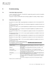
In order to commission the device, a PC with ETS is required along with a connection to the ABB i-
bus
®
, e.g. via a KNX interface.
The device is ready for operation after the bus voltage is applied. No auxiliary voltage is required.
6.2
Commissioning overview
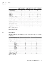
The
Fan Coil Controller, PWM, 3-speed
application is available for the Fan Coil Controller FCC/S
1.1.1.1.
The
Fan Coil Controller, PWM, 3-speed, manual operation
application is available for the Fan Coil
Controller FCC/S 1.1.2.1.
The
Fan Coil Controller, 0–10V, 3-speed
application is available for the Fan Coil Controller FCC/S
1.2.1.1.
The
Fan Coil Controller, 0–10V, 3-speed, manual operation
application is available for the Fan
Coil Controller FCC/S 1.2.2.1.
The
Fan Coil Controller, 0–10V, 0–10V
application is available for the Fan Coil Controller FCC/S
1.3.1.1.
The
Fan Coil Controller, 0–10V, 0–10V, manual operation
application is available for the Fan Coil
Controller FCC/S 1.3.2.1.
The
Fan Coil Controller, PWM, 3-speed
application is available for the Fan Coil Controller FCC/S
1.4.1.1.
The
Fan Coil Controller, PWM, 0–10V
application is available for the Fan Coil Controller FCC/S
1.5.1.1.
The
Fan Coil Controller, PWM, 0–10V, manual operation
application is available for the Fan Coil
Controller FCC/S 1.5.2.1.
ETS is required in order to parametrize the device.
For information on how to use the i-bus® Tool, see: Integration into the i-bus® Tool, Page 81
The available functions are as follows:
Additional output
For control of auxiliary electrical heating, e.g. in the winter <-> summer
transition phase.
Relay fan
A three-speed fan is controlled either with a two-way connection or with
step switching.
Continuous fan
A continuous fan is controlled by a 0…10 V analog control signal.
Thermoelectric valve
The valve drives are actuated via PWM or 3-point control. The outputs are
protected against short circuit and overload.
Analog valve
The valve drives are actuated via a 0...10 V analog control signal. The out-
puts are protected against short circuit and overload.
Inputs
There are four inputs available. These are used to monitor and/or connect,
e.g., window contacts, a condensation pan, dew point sensors or tempera-
ture sensors.
As an option, an analog room control unit can be connected to input a.
Table 30: Fan coil controller functions

