background image

ABB i-bus

®

 KNX

Group objects

FCC/S 1.X.X.1 | 2CDC 508 200 D0211 Rev A 322

8.2

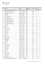
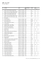
Group objects General

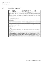
No.

Function

Group object name Data Type

Flag

1

In operation

General

1 bit

DPT 1.002

C, R, T

The group object is enabled if the parameter 

Enable group object "In operation" 1 bit

 is set to 

Yes

 in the

General

 parameter window.

In order to regularly monitor the presence of the device on the KNX, a telegram In operation is sent cyclically
on the bus.

As long as the group object is activated, it sends a parameterizable In operation telegram.

The telegram value depends on the option selected in Parameter 

Send

.

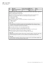
2

Status byte device

General

1 byte

Non DPT

C, R, T

This group object is always enabled and indicates the current device state. It indicates whether the device is
working normally or whether manual override is in effect.

This group object maps the following information:

Bit 0: Operating mode overridden
The controller was overridden via the group object 

Operating mode override

.

This bit is always 0 in actuator mode.

0: No override

1: Override active

Bit 1: Building Protection
The device is in Building Protection mode due to dew point/fill level alarm or an open window
This bit is always 0 in actuator mode.

0: Building protection

1: Building protection active

Bit 2: Forced operation
Forced operation was activated.

0: Forced operation inactive

1: Forced operation active

Bit 3: Manual override
The valve was manually overridden via group object.

0: Manual override inactive

1: Manual override active

Bit 4: Direct operation/membrane keypad
Manual operation via the device's membrane keypad is active
This option is available only for devices with membrane keypad

0: Manual operation inactive

1: Manual operation active

Bit 5: Security Mode
The device is in Security Mode, e.g. due to temperature value or control value failure; a defined control
value applies (s. parameter Cyclical monitoring, Page 239).

Note

When in controller mode, the device is also in Security Mode after booting up, because the controller
has not yet received a valid temperature value.

This does not depend on whether cyclic monitoring was activated for the temperature.

The device is operating normally when the group object value is 0 (= all individual bits = 0).

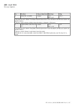
3

Not used

4

Request status values

General

1 bit

DPT 1.017

C, W

This group object is always enabled.

When this group object receives a telegram with the value 0 or 1, all group objects Status are sent on the bus
if they were parametrized with 

On request

.

Содержание i-bus FCC/S 1 1 Series

Страница 1: ... PRODUCT MANUAL ABB i bus KNX FCC S 1 X X 1 Fan Coil Controller ...

Страница 2: ...hnical data 25 3 4 4 1 General technical data 25 3 4 4 2 Device type 26 3 4 4 3 Valve outputs electrothermal PWM 26 3 4 4 4 Valve outputs motor driven 3 point 26 3 4 4 5 Rated current output 16 A 26 3 5 Fan Coil Controller FCC S 1 2 1 1 0 10V MDRC 27 3 5 1 Dimension drawing 28 3 5 2 Connection diagram 29 3 5 3 Operating and display elements 30 3 5 4 Technical data 31 3 5 4 1 General technical data...

Страница 3: ...troller FCC S 1 5 1 1 PWM MDRC 62 3 10 1 Dimension drawing 63 3 10 2 Connection diagram 64 3 10 3 Operating and display elements 65 3 10 4 Technical data 66 3 10 4 1 General technical data 66 3 10 4 2 Device type 67 3 10 4 3 Valve outputs electrothermal PWM 67 3 10 4 4 Valve outputs motor driven 3 point 67 3 10 4 5 Inputs 67 3 10 4 6 Rated current output 16 A 68 3 10 4 7 Fan output analog 68 3 11 ...

Страница 4: ...Manual operation parameter window 92 7 3 1 Manual operation 92 7 3 2 Automatically reset from manual operation to KNX operation 93 7 3 2 1 Time for automatic reset to KNX operation 93 7 4 Application 94 7 4 1 Application parameters parameter window 94 7 4 1 1 FCC S 1 1 x 1 1 5 x 1 94 7 4 1 2 FCC S 1 2 x 1 1 3 x 1 119 7 4 2 Device function parameter window 144 7 4 2 1 FCC S 1 1 2 1 1 2 2 1 144 7 4 ...

Страница 5: ... 1 1 FCC S 1 2 x 1 1 3 x 1 265 7 9 1 2 FCC S 1 1 x 1 1 5 x 1 266 7 10 Fan output parameter window 268 7 10 1 FCC S 1 1 x 1 1 2 x 1 1 4 x 1 268 7 10 1 1 Number of fan speeds 268 7 10 1 2 Fan type of operation important observe the technical data for the fan 269 7 10 1 3 Enable automatic mode based on control value 270 7 10 1 4 Enable start up behavior switch on from Off to On 275 7 10 1 5 Enable ru...

Страница 6: ... 12 2 1 Fan operation FCC S 1 1 x 1 FCC S 1 2 x 1 and FCC S 1 4 1 1 358 12 2 1 1 Fan with changeover switch 359 12 2 1 2 Fan in speed switching 360 12 2 2 Fan operation FCC S 1 3 X 1 and 1 5 X 1 360 12 2 3 Automatic operation 360 12 2 4 Direct operation 360 12 2 5 Switchover between automatic and direct operation 361 12 2 6 Speed switching logic 361 12 2 7 Fan operation functional diagram 362 12 3...

Страница 7: ...ABB i bus KNX 13 Appendix 371 13 1 Scope of delivery 371 13 2 Status byte fan 372 13 3 Status byte Valve 374 13 4 Status byte device 376 FCC S 1 X X 1 2CDC 508 200 D0211 Rev A 7 ...

Страница 8: ...ccept any responsi bility whatsoever for potential errors or possible lack of information in this document We reserve all rights in this document and in the subject matter and illustrations contained therein Reproduction transfer to third parties or processing of the content including sections thereof is not permitted without prior expressed written permission from ABB AG Copyright 2018 ABB AG All...

Страница 9: ...k hazards that will definitely result in death or serious injury unless avoided WARNING WARNING Indicates medium risk hazards that could result in death or serious injury unless avoided CAUTION CAUTION Indicates low risk hazards that could result in slight or moderate injury unless avoided NOTICE ATTENTION Indicates a risk of malfunctions or damage to property and equipment but with no risk to lif...

Страница 10: ...erate the device only in a closed housing distribution board Mounting and installation must be carried out by qualified electricians Switch off the device supply voltage before mounting 2 2 Proper use The Fan Coil Controller can be installed either centrally in an electrical distribution board or distrib uted in a fan coil unit The device is a Modular Installation Device for quick installation in ...

Страница 11: ...l C Controller S MDRC x 1 1 fold x 1 2 3 4 5 x 1 2 x x Electrothermal Valve Drive PWM 3 speed fan relay Analog valve drive 0 10 V 3 speed fan relay Analog valve drive 0 10 V continuous fan 0 10 V Electrothermal Valve Drive PWM 3 speed fan relay Electrothermal Valve Drive PWM continuous fan 0 10 V Without manual operation With manual operation Version number x 1 2 etc Table 2 Product name descripti...

Страница 12: ...ils Description MB Type Order No Packag ing unit pcs Weight 1 pc g Fan Coil Controller 6 FCC S 1 1 1 1 2CDG 110 210 R0011 1 230 Fan Coil Controller 6 FCC S 1 1 2 1 2CDG 110 211 R0011 1 235 Fan Coil Controller 6 FCC S 1 2 1 1 2CDG 110 212 R0011 1 230 Fan Coil Controller 6 FCC S 1 2 2 1 2CDG 110 213 R0011 1 235 Fan Coil Controller 6 FCC S 1 3 1 1 2CDG 110 214 R0011 1 210 Fan Coil Controller 6 FCC S ...

Страница 13: ...e device is a modular installation device MDRC in pro M design It is intended for installation in distribution boards on 35 mm mounting rails Physical address assignment and parametrization are carried out with ETS The device is powered by the ABB i bus KNX bus and requires no additional auxiliary voltage supply The device is ready for operation after connecting the bus voltage ...

Страница 14: ...ABB i bus KNX Product Overview FCC S 1 X X 1 2CDC 508 200 D0211 Rev A 14 3 3 1 Dimension drawing 105 Fig 2 Dimension drawing 2CDC072026F0017 ...

Страница 15: ...4 a b c 17 16 d 8 9 6 7 5 Un2 F C D E U 230 V n1 2 I 16 A n2 I 0 5 A n U 24 230 V n 4 Un1 I 5 A n1 L3 L2 N L1 10 Fig 3 FCC S 1 1 1 1 2CDC072011F0017 Legend 1 Label carrier 2 Programming LED 3 Programming button 4 Bus connection terminal 5 Cover cap 6 Inputs a b c d 7 Valve output A 8 Valve output B 9 Fan output 10 Auxiliary relay ...

Страница 16: ... S 1 X X 1 2CDC 508 200 D0211 Rev A 16 3 3 3 Operating and display elements Button LED Description Function LED indicator Assignment of the physical address On Device is in programming mode Table 5 Operating and display elements general ...

Страница 17: ...lass Degree of protection IP 20 to EN 60529 Protection class II to EN 61140 Isolation category Overvoltage category III to EN 60664 1 Pollution degree II to EN 60664 1 SELV KNX safety extra low voltage SELV 24 V DC Temperature range Operation 5 45 C Transport 25 70 C Storage 25 55 C Ambient conditions Maximum air humidity 93 no condensation allowed Atmospheric pressure Atmosphere up to 2 000 m Des...

Страница 18: ...n floating Yes Un rated voltage 24 230 V AC 50 60 Hz In rated current per output pair 0 5 A Continuous current at Tu up to 20 C 0 25 A resistive load per channel Continuous current at Tu up to 45 C 0 15 A resistive load per channel Starting current Maximum 1 6 A 10 s at Tu up to 45 C Tu ambient temperature Minimum load 1 2 VA per output 3 3 4 5 Rated current output 16 A Rated values Number 1 Un2 r...

Страница 19: ...e device is a modular installation device MDRC in pro M design It is intended for installation in distribution boards on 35 mm mounting rails Physical address assignment and parametrization are carried out with ETS The device is powered by the ABB i bus KNX bus and requires no additional auxiliary voltage supply The device is ready for operation after connecting the bus voltage ...

Страница 20: ...ABB i bus KNX Product Overview FCC S 1 X X 1 2CDC 508 200 D0211 Rev A 20 3 4 1 Dimension drawing 105 Fig 5 Dimension drawing 2CDC072026F0017 ...

Страница 21: ...0 11 15 12 13 14 16 Fig 6 FCC S 1 1 2 1 2CDC072012F0017 Legend 1 Label carrier 2 Programming LED 3 Programming button 4 Bus connection terminal 5 Cover cap 6 Inputs a b c d 7 Valve output A 8 Valve output B 9 Fan output 10 Auxiliary relay 11 Valve output changeover button LED 12 Valve output open close button LED 13 Relay output open close button LED 14 Switch fan speed button LED 15 Manual operat...

Страница 22: ...e parameters it is not possible to select the valve On Indicates the selected valve Flashing Error overload short cir cuit on the output concerned Open valve output Maximum valve control value 100 set Reset both outputs Button must be pressed for at least 5 seconds On Valve control value at 100 Flashing Indicates a fault e g overload short circuit Close valve output Minimum valve control value 0 i...

Страница 23: ...n Contact closed LED off Contact open Temperature sensor LED on Temperature sensor connected LED flashing Error cable break short circuit Analog room control unit LED on Analog room control unit connected LED flashing Error cable break short circuit Table 7 Operating and display elements manual operation KNX operation Button LED Description Function LED indicator Valve output changeover Switches b...

Страница 24: ...er switching Speed 0 all LEDs off Speed 1 LED 1 on Speed 2 LED 2 on Speed 3 LED 3 on Manual operation Activate manual operation by pressing and holding the button for at least 5 seconds On On The device is in Manual Off Device is in KNX mode Flashing when button is pressed Manual operation has been deacti vated via ETS parameters Inputs a x LED indication depending on how the inputs are used Binar...

Страница 25: ...ass Degree of protection IP 20 to EN 60529 Protection class II to EN 61140 Isolation category Overvoltage category III to EN 60664 1 Pollution degree II to EN 60664 1 SELV KNX safety extra low voltage SELV 24 V DC Temperature range Operation 5 45 C Transport 25 70 C Storage 25 55 C Ambient conditions Maximum air humidity 93 no condensation allowed Atmospheric pressure Atmosphere up to 2 000 m Desi...

Страница 26: ...er 1 non floating Yes Un rated voltage 24 230 V AC 50 60 Hz In rated current per output pair 0 5 A Continuous current at Tu up to 20 C 0 25 A resistive load per channel Continuous current at Tu up to 45 C 0 15 A resistive load per channel Starting current Maximum 1 6 A 10 s at Tu up to 45 C Minimum load 1 2 VA per PWM output 3 4 4 5 Rated current output 16 A Rated values Number 1 Un2 rated voltage...

Страница 27: ...he device is a modular installation device MDRC in pro M design It is intended for installation in distribution boards on 35 mm mounting rails Physical address assignment and parametrization are carried out with ETS The device is powered by the ABB i bus KNX bus and requires no additional auxiliary voltage supply The device is ready for operation after connecting the bus voltage ...

Страница 28: ...ABB i bus KNX Product Overview FCC S 1 X X 1 2CDC 508 200 D0211 Rev A 28 3 5 1 Dimension drawing 105 Fig 8 Dimension drawing 2CDC072026F0017 ...

Страница 29: ...17 d 9 10 7 8 6 Un2 F C D E 5 Un1 1 3 2 A B 4 0 10 V 0 10 V I 2 16 A n I 5 A n1 U 230 V n1 2 0 V N L3 L2 10 Fig 9 FCC S 1 2 1 1 2CDC072013F0017 Legend 1 Label carrier 2 Programming LED 3 Programming button 4 Bus connection terminal 5 Cover cap 6 Inputs a b c d 7 Valve output A 8 Valve output B 9 Fan output 10 Auxiliary relay ...

Страница 30: ... S 1 X X 1 2CDC 508 200 D0211 Rev A 30 3 5 3 Operating and display elements Button LED Description Function LED indicator Assignment of the physical address On Device is in programming mode Table 9 Operating and display elements general ...

Страница 31: ... protection IP 20 to EN 60529 Protection class II to EN 61140 Isolation category Overvoltage category III to EN 60664 1 Pollution degree II to EN 60664 1 SELV KNX safety extra low voltage SELV 24 V DC Temperature range Operation 5 45 C Transport 25 70 C Storage 25 55 C Ambient conditions Maximum air humidity 93 no condensation allowed Atmospheric pressure Atmosphere up to 2 000 m Design Modular in...

Страница 32: ...Y 2k NI 1k NTC 20k Line length between sensor and device input Max 100 m one way 3 5 4 4 Rated current output 16 A Rated values Number 1 Un2 rated voltage 250 V AC 50 60 Hz In2 rated current per output pair 16 A resistive load for additional heater Switching currents AC3 operation cos ϕ 0 45 to EN 60947 4 1 16 A 230 V AC AC1 operation cos ϕ 0 8 to EN 60947 4 1 16 A 230 V AC Minimum switching capac...

Страница 33: ...he device is a modular installation device MDRC in pro M design It is intended for installation in distribution boards on 35 mm mounting rails Physical address assignment and parametrization are carried out with ETS The device is powered by the ABB i bus KNX bus and requires no additional auxiliary voltage supply The device is ready for operation after connecting the bus voltage ...

Страница 34: ...ABB i bus KNX Product Overview FCC S 1 X X 1 2CDC 508 200 D0211 Rev A 34 3 6 1 Dimension drawing 105 Fig 11 Dimension drawing 2CDC072026F0017 ...

Страница 35: ...15 12 13 14 16 Fig 12 FCC S 1 2 2 1 2CDC072014F0017 Legend 1 Label carrier 2 Programming LED 3 Programming button 4 Bus connection terminal 5 Cover cap 6 Inputs a b c d 7 Valve output A 8 Valve output B 9 Fan output 10 Auxiliary relay 11 Valve output changeover button LED 12 Valve output open close button LED 13 Relay output open close button LED 14 Switch fan speed button LED 15 Manual operation ...

Страница 36: ...he parameters it is not possible to select the valve On Indicates the selected valve Flashing Error overload short cir cuit on the output concerned Open valve output Maximum valve control value 100 set Reset both outputs Button must be pressed for at least 5 seconds On Valve control value at 100 Flashing Indicates a fault e g overload short circuit Close valve output Minimum valve control value 0 ...

Страница 37: ...n Contact closed LED off Contact open Temperature sensor LED on Temperature sensor connected LED flashing Error cable break short circuit Analog room control unit LED on Analog room control unit connected LED flashing Error cable break short circuit Table 11 Operating and display elements manual operation KNX operation Button LED Description Function LED indicator Valve output changeover Switches ...

Страница 38: ...r switching Speed 0 all LEDs off Speed 1 LED 1 on Speed 2 LED 2 on Speed 3 LED 3 on Manual operation Activate manual operation by pressing and holding the button for at least 5 seconds On On The device is in Manual Off Device is in KNX mode Flashing when button is pressed Manual operation has been deacti vated via ETS parameters Inputs a x LED indication depending on how the inputs are used Binary...

Страница 39: ... protection IP 20 to EN 60529 Protection class II to EN 61140 Isolation category Overvoltage category III to EN 60664 1 Pollution degree II to EN 60664 1 SELV KNX safety extra low voltage SELV 24 V DC Temperature range Operation 5 45 C Transport 25 70 C Storage 25 55 C Ambient conditions Maximum air humidity 93 no condensation allowed Atmospheric pressure Atmosphere up to 2 000 m Design Modular in...

Страница 40: ... KT 1k KTY 2k NI 1k NTC 20k Line length between sensor and device input Max 100 m one way 3 6 4 4 Rated current output 16 A Rated values Number 1 Un2 rated voltage 250 V AC 50 60 Hz In2 rated current per output pair 16 A resistive load for additional heater Switching currents AC3 operation cos ϕ 0 45 to EN 60947 4 1 16 A 230 V AC AC1 operation cos ϕ 0 8 to EN 60947 4 1 16 A 230 V AC Minimum switch...

Страница 41: ...he device is a modular installation device MDRC in pro M design It is intended for installation in distribution boards on 35 mm mounting rails Physical address assignment and parametrization are carried out with ETS The device is powered by the ABB i bus KNX bus and requires no additional auxiliary voltage supply The device is ready for operation after connecting the bus voltage ...

Страница 42: ...ABB i bus KNX Product Overview FCC S 1 X X 1 2CDC 508 200 D0211 Rev A 42 3 7 1 Dimension drawing 105 Fig 14 Dimension drawing 2CDC072026F0017 ...

Страница 43: ... C A B 4 0 V 0 10 V 0 10 V I 16 A n1 U 230 V n1 0 10 V C 7 11 13 15 10 12 14 a b c 17 16 d N L2 L1 10 Fig 15 FCC S 1 3 1 1 2CDC072015F0017 Legend 1 Label carrier 2 Programming LED 3 Programming button 4 Bus connection terminal 5 Cover cap 6 Inputs a b c d 7 Valve output A 8 Valve output B 9 Fan output 10 Auxiliary relay ...

Страница 44: ...S 1 X X 1 2CDC 508 200 D0211 Rev A 44 3 7 3 Operating and display elements Button LED Description Function LED indicator Assignment of the physical address On Device is in programming mode Table 13 Operating and display elements general ...

Страница 45: ...ion IP 20 to EN 60529 Protection class II to EN 61140 Isolation category Overvoltage category III to EN 60664 1 Pollution degree II to EN 60664 1 SELV KNX safety extra low voltage SELV 24 V DC Temperature range Operation 5 45 C Transport 25 70 C Storage 25 55 C Ambient conditions Maximum air humidity 93 no condensation allowed Atmospheric pressure Atmosphere up to 2 000 m Design Modular installati...

Страница 46: ...current output 16 A Rated values Number 1 Un2 rated voltage 250 V AC 50 60 Hz In2 rated current per output pair 16 A resistive load for additional heater Switching currents AC3 operation cos ϕ 0 45 to EN 60947 4 1 16 A 230 V AC AC1 operation cos ϕ 0 8 to EN 60947 4 1 16 A 230 V AC Minimum switching capacity at 100 mA 24 V AC DC current switching capacity resistive load at 16 A 24 V DC Service life...

Страница 47: ... 4 6 Fan output analog Rated values Number 1 non isolated short circuit proofed Control signal 0 10 V DC Signal type Analog Output load 10 kohms Output tolerance 10 Current limitation max 1 5 mA FCC S 1 X X 1 2CDC 508 200 D0211 Rev A 47 ...

Страница 48: ...he device is a modular installation device MDRC in pro M design It is intended for installation in distribution boards on 35 mm mounting rails Physical address assignment and parametrization are carried out with ETS The device is powered by the ABB i bus KNX bus and requires no additional auxiliary voltage supply The device is ready for operation after connecting the bus voltage ...

Страница 49: ...ABB i bus KNX Product Overview FCC S 1 X X 1 2CDC 508 200 D0211 Rev A 49 3 8 1 Dimension drawing 105 Fig 17 Dimension drawing 2CDC072026F0017 ...

Страница 50: ...13 14 16 Fig 18 FCC S 1 3 2 1 2CDC072016F0017 Legend 1 Label carrier 2 Programming LED 3 Programming button 4 Bus connection terminal 5 Cover cap 6 Inputs a b c d 7 Valve output A 8 Valve output B 9 Fan output 10 Auxiliary relay 11 Valve output changeover button LED 12 Valve output open close button LED 13 Relay output open close button LED 14 Switch fan speed button LED 15 Manual operation button...

Страница 51: ... the parameters it is not possible to select the valve On Indicates the selected valve Flashing Error overload short cir cuit on the output concerned Open valve output Maximum valve control value 100 set Reset both outputs Button must be pressed for at least 5 seconds On Valve control value at 100 Flashing Indicates a fault e g overload short circuit Close valve output Minimum valve control value ...

Страница 52: ...ing Error cable break short circuit Analog room control unit LED on Analog room control unit connected LED flashing Error cable break short circuit Table 15 Operating and display elements manual operation KNX operation Button LED Description Function LED indicator Valve output changeover Switches between valve A and valve B If a valve output has been disabled in the parameters it is not possible t...

Страница 53: ...on Speed 2 LED 2 on Speed 3 LED 3 on Manual operation Activate manual operation by pressing and holding the button for at least 5 seconds On On The device is in Manual Off Device is in KNX mode Flashing when button is pressed Manual operation has been deacti vated via ETS parameters Inputs a x LED indication depending on how the inputs are used Binary sensor LED on Contact closed LED off Contact o...

Страница 54: ...ion IP 20 to EN 60529 Protection class II to EN 61140 Isolation category Overvoltage category III to EN 60664 1 Pollution degree II to EN 60664 1 SELV KNX safety extra low voltage SELV 24 V DC Temperature range Operation 5 45 C Transport 25 70 C Storage 25 55 C Ambient conditions Maximum air humidity 93 no condensation allowed Atmospheric pressure Atmosphere up to 2 000 m Design Modular installati...

Страница 55: ... 4 Rated current output 16 A Rated values Number 1 Un2 rated voltage 250 V AC 50 60 Hz In2 rated current per output pair 16 A resistive load for additional heater Switching currents AC3 operation cos ϕ 0 45 to EN 60947 4 1 16 A 230 V AC AC1 operation cos ϕ 0 8 to EN 60947 4 1 16 A 230 V AC Minimum switching capacity at 100 mA 24 V AC DC current switching capacity resistive load at 16 A 24 V DC Ser...

Страница 56: ...e device is a modular installation device MDRC in pro M design It is intended for installation in distribution boards on 35 mm mounting rails Physical address assignment and parametrization are carried out with ETS The device is powered by the ABB i bus KNX bus and requires no additional auxiliary voltage supply The device is ready for operation after connecting the bus voltage ...

Страница 57: ...ABB i bus KNX Product Overview FCC S 1 X X 1 2CDC 508 200 D0211 Rev A 57 3 9 1 Dimension drawing 105 Fig 20 Dimension drawing 2CDC072026F0017 ...

Страница 58: ...ram 6 4 5 3 Un1 B C D 1 2 Un A 8 10 12 7 9 11 a b c 14 13 d U 230 V n1 I 5 A n1 I 0 5 A n U 24 230 V n N L2 N L1 Fig 21 FCC S 1 4 1 1 2CDC072017F0017 Legend 1 Label carrier 2 Programming LED 3 Programming button 4 Bus connection terminal 5 Cover cap 6 Inputs a b c d 7 Valve output A 9 Fan output ...

Страница 59: ...S 1 X X 1 2CDC 508 200 D0211 Rev A 59 3 9 3 Operating and display elements Button LED Description Function LED indicator Assignment of the physical address On Device is in programming mode Table 17 Operating and display elements general ...

Страница 60: ...e of protection IP 20 to EN 60529 Protection class II to EN 61140 Isolation category Overvoltage category III to EN 60664 1 Pollution degree II to EN 60664 1 SELV KNX safety extra low voltage SELV 24 V DC Temperature range Operation 5 45 C Transport 25 70 C Storage 25 55 C Ambient conditions Maximum air humidity 93 no condensation allowed Atmospheric pressure Atmosphere up to 2 000 m Design Modula...

Страница 61: ... 230 V AC 50 60 Hz In rated current per output pair 0 5 A Continuous current at Tu up to 20 C 0 25 A resistive load per channel Continuous current at Tu up to 45 C 0 15 A resistive load per channel Starting current Maximum 1 6 A 10 s at Tu up to 45 C Standard title Tu ambient temperature Minimum load 1 2 VA per PWM output 3 9 4 4 Inputs For Analog Room Controller Number 1 Contact scanning Scanning...

Страница 62: ...he device is a modular installation device MDRC in pro M design It is intended for installation in distribution boards on 35 mm mounting rails Physical address assignment and parametrization are carried out with ETS The device is powered by the ABB i bus KNX bus and requires no additional auxiliary voltage supply The device is ready for operation after connecting the bus voltage ...

Страница 63: ...ABB i bus KNX Product Overview FCC S 1 X X 1 2CDC 508 200 D0211 Rev A 63 3 10 1 Dimension drawing 105 Fig 23 Dimension drawing 2CDC072026F0017 ...

Страница 64: ... d Un1 D N C C 7 8 5 6 0 V 0 10 V 4 1 3 2 Un A B U 230 V n1 I 16 A n1 I 0 5 A n U 24 230 V n N L1 N L3 L2 10 Fig 24 FCC S 1 5 1 1 2CDC072018F0017 Legend 1 Label carrier 2 Programming LED 3 Programming button 4 Bus connection terminal 5 Cover cap 6 Inputs a b c d 7 Valve output A 8 Valve output B 9 Fan output 10 Auxiliary relay ...

Страница 65: ...S 1 X X 1 2CDC 508 200 D0211 Rev A 65 3 10 3 Operating and display elements Button LED Description Function LED indicator Assignment of the physical address On Device is in programming mode Table 18 Operating and display elements general ...

Страница 66: ...ree of protection IP 20 to EN 60529 Protection class II to EN 61140 Isolation category Overvoltage category III to EN 60664 1 Pollution degree II to EN 60664 1 SELV KNX safety extra low voltage SELV 24 V DC Temperature range Operation 5 45 C Transport 25 70 C Storage 25 55 C Ambient conditions Maximum air humidity 93 no condensation allowed Atmospheric pressure Atmosphere up to 2 000 m Design Modu...

Страница 67: ...g current Maximum 1 6 A 10 s at Tu up to 45 C Standard title Tu ambient temperature Minimum load 1 2 VA per PWM output 3 10 4 4 Valve outputs motor driven 3 point Rated values Number 1 non floating Yes Un rated voltage 24 230 V AC 50 60 Hz In rated current per output pair 0 5 A Continuous current at Tu up to 20 C 0 25 A resistive load per channel Continuous current at Tu up to 45 C 0 15 A resistiv...

Страница 68: ...A 24 V AC DC current switching capacity resistive load at 16 A 24 V DC Service life Mechanical service life 3 x 10 cycles Electrical endurance of switching contacts to IEC 60947 4 1 10 cycles AC1 240 V cos ϕ 0 8 10 cycles Switching times Maximum relay position change per output and minute if only one relay is switched 500 3 10 4 7 Fan output analog Rated values Number 1 non isolated short circuit ...

Страница 69: ...he device is a modular installation device MDRC in pro M design It is intended for installation in distribution boards on 35 mm mounting rails Physical address assignment and parametrization are carried out with ETS The device is powered by the ABB i bus KNX bus and requires no additional auxiliary voltage supply The device is ready for operation after connecting the bus voltage ...

Страница 70: ...ABB i bus KNX Product Overview FCC S 1 X X 1 2CDC 508 200 D0211 Rev A 70 3 11 1 Dimension drawing 105 Fig 26 Dimension drawing 2CDC072026F0017 ...

Страница 71: ... 15 12 13 14 16 Fig 27 FCC S 1 5 2 1 2CDC072019F0017 Legend 1 Label carrier 2 Programming LED 3 Programming button 4 Bus connection terminal 5 Cover cap 6 Inputs a b c d 7 Valve output A 8 Valve output B 9 Fan output 10 Auxiliary relay 11 Valve output changeover button LED 12 Valve output open close button LED 13 Relay output open close button LED 14 Switch fan speed button LED 15 Manual operation...

Страница 72: ... the parameters it is not possible to select the valve On Indicates the selected valve Flashing Error overload short cir cuit on the output concerned Open valve output Maximum valve control value 100 set Reset both outputs Button must be pressed for at least 5 seconds On Valve control value at 100 Flashing Indicates a fault e g overload short circuit Close valve output Minimum valve control value ...

Страница 73: ...ing Error cable break short circuit Analog room control unit LED on Analog room control unit connected LED flashing Error cable break short circuit Table 20 Operating and display elements manual operation KNX operation Button LED Description Function LED indicator Valve output changeover Switches between valve A and valve B If a valve output has been disabled in the parameters it is not possible t...

Страница 74: ...on Speed 2 LED 2 on Speed 3 LED 3 on Manual operation Activate manual operation by pressing and holding the button for at least 5 seconds On On The device is in Manual Off Device is in KNX mode Flashing when button is pressed Manual operation has been deacti vated via ETS parameters Inputs a x LED indication depending on how the inputs are used Binary sensor LED on Contact closed LED off Contact o...

Страница 75: ...ree of protection IP 20 to EN 60529 Protection class II to EN 61140 Isolation category Overvoltage category III to EN 60664 1 Pollution degree II to EN 60664 1 SELV KNX safety extra low voltage SELV 24 V DC Temperature range Operation 5 45 C Transport 25 70 C Storage 25 55 C Ambient conditions Maximum air humidity 93 no condensation allowed Atmospheric pressure Atmosphere up to 2 000 m Design Modu...

Страница 76: ...sistive load per channel Starting current Maximum 1 6 A 10 s at Tu up to 45 C Standard title Minimum load 1 2 VA per PWM output 3 11 4 4 Valve outputs motor driven 3 point Rated values Number 1 non floating Yes Un rated voltage 24 230 V AC 50 60 Hz In rated current per output pair 0 5 A Continuous current at Tu up to 20 C 0 25 A resistive load per channel Continuous current at Tu up to 45 C 0 15 A...

Страница 77: ...A 24 V AC DC current switching capacity resistive load at 16 A 24 V DC Service life Mechanical service life 3 x 10 cycles Electrical endurance of switching contacts to IEC 60947 4 1 10 cycles AC1 240 V cos ϕ 0 8 10 cycles Switching times Maximum relay position change per output and minute if only one relay is switched 500 3 11 4 7 Fan output analog Rated values Number 1 non isolated short circuit ...

Страница 78: ...le switch over delay is provided for this pur pose Three phase drives are not supported Four inputs are available for connecting temperature sensors and for monitoring a window contact condensate formation or a collection pan Additionally one of the inputs can be used to connect a local analog room control unit SAF A or SAR A Such a device can be used for local adjustment of the setpoint temperatu...

Страница 79: ... 2 2 Electrothermal Valve Drives PWM 2 2 1 2 2 Motor Driven Valve Drives 3 point 1 1 1 1 Analog outputs 0 10 V 2 2 2 2 Analog Valve Drives 2 2 2 2 Table 22 Functional overview For more information see 4 3 Input functions The following table provides an overview of the functions possible with the inputs of the FCC S and the application Function a b c d Connection of analog room control unit X Binar...

Страница 80: ...ion Overload short circuit X X Table 24 Valve output function FCC S 1 4 1 1 Function A Electrothermal Valve Drive PWM X Solenoid valve open close X Error detection Overload short circuit X Table 25 Valve output function FCC S 1 2 X 1 and FCC S 1 3 X 1 Function A B Analog valve drive 0 10 V X X 1 10 V X X 2 10 V X X 10 0 V X X 6 way valve drive X VAV damper drive control signal X X Error detection ...

Страница 81: ...nput X Table 29 Function of the relay output 4 5 Integration into the i bus Tool The device possesses and interface to the i bus Tool The i bus Tool can be used to read out data and test functions on the connected device In addition values can be simulated for test purposes If there is no communication output values are no longer sent to the bus even if they are simulated using the i bus Tool The ...

Страница 82: ... 1 Bus voltage failure Bus voltage failure describes the sudden drop in failure of the bus voltage e g due to a power fail ure 4 6 1 2 Bus voltage recovery Bus voltage recovery is the state after bus voltage is restored after failing previously due to a bus voltage failure 4 6 1 3 ETS reset Generally an ETS reset is defined as a reset of the device via ETS The ETS reset is triggered in the ETS und...

Страница 83: ...e device has a maximum current consumption of 12 mA DANGER Severe injuries due to touch voltage Feedback from differing phase conductors can produce touch voltages and lead to severe in juries Operate the device only in a closed housing distribution board Disconnect all phases before working on the electrical connection 5 2 Mounting on DIN rail The device is held and removed exclusively without au...

Страница 84: ... 508 200 D0211 Rev A 84 5 3 Supplied state The device is supplied with the physical address 15 15 255 The application is preloaded The complete application can be downloaded again if required Downloads may take longer after a change of application or unloading ...

Страница 85: ...ion is available for the Fan Coil Controller FCC S 1 4 1 1 The Fan Coil Controller PWM 0 10V application is available for the Fan Coil Controller FCC S 1 5 1 1 The Fan Coil Controller PWM 0 10V manual operation application is available for the Fan Coil Controller FCC S 1 5 2 1 ETS is required in order to parametrize the device For information on how to use the i bus Tool see Integration into the i...

Страница 86: ...6 4 Software application 6 4 1 Download response Due to the complexity of the device the progress bar for the download may take up to one and a half minutes before it appears depending on the PC used 6 4 2 Copying exchanging and converting The ABB Update Copy Convert application can be used to copy or exchange parameter settings and to convert the application version The application is available f...

Страница 87: ...ilation air conditioning Fan Coil Controller The following chapters describe the device parameters based on the parameter windows Parame ter windows are structured dynamically so that further parameters may be enabled depending on the parameterization and function of the outputs The default values of the parameters are underlined e g Options yes no Note The applications for devices with manual ope...

Страница 88: ...ts is set to cor respond with the parameterization or the group object values If group objects are read out via the bus during the sending and switching delay e g by a visual display system these requests are stored and a response is sent once the delay time has expired An initialization time of about two seconds is included in the delay time The initialization time is the time that the processor ...

Страница 89: ...time The telegrams are sent as quickly as possible at the start of a period Note The device counts the number of telegrams sent within the parametrized period As soon as the maximum number of sent telegrams is reached no further telegrams are sent on the KNX bus until the end of the period A new period commences at the end of the previous period The tele gram counter is reset to zero and sending o...

Страница 90: ...eriod The tele gram counter is reset to zero and sending of telegrams is allowed again The current group ob ject value at the time of sending is always sent The first period break time is not precisely predefined It can be anywhere between zero sec onds and the parametrized time The subsequent sending times correspond with the parametrized time Example Maximum number of sent telegrams 5 period 5 s...

Страница 91: ...ends its value after the sending and switching delay set 7 2 5 Access to i bus Tool Options Deactivated Value display only Full access This parameter is used to restrict or forbid completely access by the ABB i bus Tool If Deacti vated is selected access by the i bus Tool is completely disabled If Value display only is selected no values can be changed by the i bus Tool only the status is displaye...

Страница 92: ...ion button on the device Enabled The operating states Manual operation and KNX operation can be switched over via the Manual operation button The Enable disable manual operation and Status Manual operation group objects are enabled The Enable disable manual operation group object makes it possible to enable or disable man ual operation via the bus The Status Manual operation group object indicates...

Страница 93: ...back to KNX operation Yes The device is reset to KNX operation depending on the parameterized time 7 3 2 1 Dependent Parameter Time for automatic reset to KNX operation Options 00 00 30 00 05 00 18 12 15 This parameter determines how long after pressing the Manual operation button the device will remain in Manual operation The device remains in Manual operation after the last button press until ei...

Страница 94: ...rs parameter window The basic settings necessary for the application are made in the Application parameters parameter window Fig 31 Application parameters parameter window DESTO001875 7 4 1 1 FCC S 1 1 x 1 1 5 x 1 The following explanations only apply to FCC S 1 1 1 1 FCC S 1 1 2 1 FCC S 1 5 1 1 FCC S 1 5 2 1 ...

Страница 95: ...this mode the device operates independently based only on the states e g tem perature measured on the inputs or received via KNX and the setpoints operating mode changeovers received via KNX The necessary control values for the outputs are calculated in dependently from this information The Temperature controller and Setpoint manager parameter windows as well as group ob jects for the master slave...

Страница 96: ...used as the heating stage The Basic heating stage control value type parameter is pre parameterized to PI continuous 0 100 with the corresponding P and I proportions Electric heater in room This option should be selected if an electric heater in the room is used as the heating stage and for this heater the fan does not need to run as well in operation The Basic heating stage control value type par...

Страница 97: ...changeover Use 6 way valve only FCC S 1 2 x 1 1 3 x 1 Actuate basic stage heating via Note On the selection of the Fan coil unit electric heater or Fan coil unit Water heating coil options the fan follows the valve control value for this stage if the automatic mode is active On the selection of the Free configuration option this can also be set via a parameter ...

Страница 98: ... heater in the room is used as the additional stage heating and for this heater the fan does not need to run as well in opera tion The Additional stage heating control value type parameter is pre parameterized to 2 point 1 bit On Off Free configuration With this option it is possible to select freely the type of additional stage heating and also the type of control This option can be selected if t...

Страница 99: ...ons Free configuration With this option it is possible to select freely the type of basic stage cooling and also the type of control This option can be selected if the type of application is not entirely clear or if specific adjustments are necessary The Basic stage cooling control value type parameter is pre configured to PI continuous 0 100 however it is possible to select freely between all con...

Страница 100: ...ter is pre parameterized to PI continu ous 0 100 with the corresponding P and I proportions Free configuration With this option it is possible to select freely the type of additional stage cooling and also the type of control This option can be selected if the type of application is not entirely clear or if specific adjustments are necessary The Additional stage cooling control value type paramete...

Страница 101: ...is parameter is not visible if the Basic stage heating or Basic stage cooling parameters are de activated Options Automatically Via object only Via slave and via object The standard value for this parameter depends on the selection in the Type of heating cooling system parameter Selection of 4 pipe Automatically If the Automatically option is selected the changeover is only made by the controller ...

Страница 102: ...cted the control value is output directly on this physical output where it is con verted into the corresponding output signal The outputs A and B are used to actuate valve drives while the relay output is used to actuate an electric heater In parallel to the actuation via the corresponding internal output the control value is also output via the related Status Control value Basic stage heating gro...

Страница 103: ...y this statement also applies on the selection of Internal output B valve Only FCC S 1 2 x 1 1 3 x 1 If the Use 6 way valve parameter has been parameterized with Yes this parameter is pre set to Internal output A valve and cannot be changed Selection in the Type of heating cooling system parameter 2 pipe In a 2 pipe system heating and cooling are undertaken using the same device e g fan coil unit ...

Страница 104: ...tage cooling param eters it may not be possible to select all options If one of the outputs has already been selected here then it cannot also be used as an output for the additional stage heating Example If the Internal output A valve option has been selected as the output for the basic stage heating this cannot be selected as the output for the additional stage heating 2 pipe system selection in...

Страница 105: ... not be possible to select all options If one of the out puts has already been selected here then it cannot also be used as an output for the basic stage cooling Example If the Internal output A valve option has been selected as the output for the basic stage heating this cannot be selected as the output for the additional stage cooling Conversely this statement also applies on the selection of In...

Страница 106: ...ed to blow heated air into the room Without the fan running there is a risk of overheating which may lead to damage to the building or the risk of a fire To prevent this situation from arising suitable measures must be taken e g temperature moni toring with mechanical shutdown 7 4 1 1 1 1 9 1 Dependent Parameter Automatic reset of manual relay overdrive to controller operation after This parameter...

Страница 107: ...ated If several inputs have been parameterized as a window contact there is a logical OR link be tween these inputs As soon as one of the contacts signals the status Window open the con troller evaluates the status as Window open Conversely if all inputs signal the status Window closed the controller evaluates the status as Window closed Via group object The window status is received via a group o...

Страница 108: ...nputs has been parameterized for a dew point sensor The status of the dew point sen sor connected to this input is included in the control The message Configure in Inputs parameter window appears Note Only device inputs that have been parameterized as a dew point sensor are detected as such If no input has been parameterized as a dew point sensor the function is considered deactivated If several i...

Страница 109: ...t alarm status with the shutdown of the cool ing and a changeover to Building Protection mode This mode applies until the dew point alarm is cleared However a change to the heating mode if possible is allowed at any time Here the de vice continues to operate normally because the dew point only relates to the cooling and heating counteracts the dropping below the dew point temperature Note The dew ...

Страница 110: ...l level sensor The status of the fill level sensor connected to this input is included in the control The message Configure in Inputs parameter window appears Note Only device inputs that have been parameterized as a fill level sensor are detected as such If no input has been parameterized as a fill level sensor the function is considered deactivated If several inputs have been parameterized as a ...

Страница 111: ... level alarm status with the shutdown of the cool ing and a changeover to Building Protection mode This mode applies until the fill level alarm is cleared However a change to the heating mode if possible is allowed at any time Here the de vice continues to operate normally because the fill level only relates to the cooling Note A fill level sensor is used e g to monitor a condensation tray fitted ...

Страница 112: ...mperature input objects is enabled Via physical device input and group object If this option is selected the controller checks which of the physical device inputs have been parameterized as a temperature sensor Temperature values can also be received via the bus The values measured on the inputs and received via the bus are weighted The message Configure in Inputs parameter window appears The depe...

Страница 113: ...he External temperature 1 group object is the actual temperature If the 2 option has been selected the dependent parameters Weighting of external measurement 1 and Weighting of external measurement 2 are enabled 7 4 1 1 1 1 13 2 Dependent Parameter Internal measurement weighting This parameter is only visible if in the Temperature input parameter the Via physical device input and group object opti...

Страница 114: ...ighting 20 Value 2 25 C weighting 80 20 C 0 2 25 C 0 8 0 8 0 2 24 C Example 2 3 values If 50 is entered as the weighting for all three values all values have the same weight ing and a mean value is simply formed from the three values Example 3 2 values The weighting 80 applies to value 1 and the weighting 40 to value 2 value 1 is therefore taken into account in the calculation with twice the weigh...

Страница 115: ...se 6 way valve only FCC S 1 2 x 1 1 3 x 1 Actuate basic stage heating via Note On the selection of the Fan coil unit electric heater or Fan coil unit Water heating coil options the fan follows the valve control value for this stage if the automatic mode is active On the selection of the Free configuration option this can also be set via a parameter 7 4 1 1 1 2 2 Dependent Parameter Basic stage coo...

Страница 116: ...upply the device with hot and cold water It is therefore only ever possible to heat or cool a changeover is necessary to change It follows that the device is not allowed to decide on a change between heating and cooling and the changeover must always be made via the bus The Heating Cooling changeover parameter is correspondingly parameterized to Via object only and cannot be changed 4 pipe This op...

Страница 117: ...Switch relay output independently of fan speed including when fan 0 This parameter is only visible if the Internal relay output has been selected for Actuate basic stage heating via Options No Yes This parameter is used to set whether switching of the relay output is to be allowed independently of whether the fan is running or not The switching is undertaken via the dependent object Switch relay g...

Страница 118: ...uding when fan 0 parameter Options 00 00 30 00 05 00 18 12 15 This parameter defines when switching of the relay outside the control is to be reset and controller operation activated again For the time stated here the relay output can be overridden via the group object Only after this time has elapsed is the control value specified by the controller applied again for the relay A change in the oper...

Страница 119: ... S 1 X X 1 2CDC 508 200 D0211 Rev A 119 7 4 1 2 FCC S 1 2 x 1 1 3 x 1 The following explanations only apply to FCC S 1 2 1 1 FCC S 1 2 2 1 FCC S 1 3 1 1 FCC S 1 3 2 1 Fig 33 Application parameters parameter window 2CDC078009F0218 ...

Страница 120: ...uts or received via KNX and the setpoints operating mode changeovers received via KNX The necessary control values for the outputs are calculated in dependently from this information The Temperature controller and Setpoint manager parameter windows as well as group ob jects for the master slave communication are activated Here the device acts as a master Actuator device In this mode the device act...

Страница 121: ...r the fan does not need to run as well in operation The Basic heating stage control value type parameter is pre parameterized to 2 point 1 bit On Off Free configuration With this option it is possible to select freely the type of heating stage and also the type of control This option can be selected if the type of application is not entirely clear or if specific adjustments are necessary The Basic...

Страница 122: ...c heater in the room is used as the additional stage heating and for this heater the fan does not need to run as well in opera tion The Additional stage heating control value type parameter is pre parameterized to 2 point 1 bit On Off Free configuration With this option it is possible to select freely the type of additional stage heating and also the type of control This option can be selected if ...

Страница 123: ...ons Free configuration With this option it is possible to select freely the type of basic stage cooling and also the type of control This option can be selected if the type of application is not entirely clear or if specific adjustments are necessary The Basic stage cooling control value type parameter is pre configured to PI continuous 0 100 however it is possible to select freely between all con...

Страница 124: ...ter is pre parameterized to PI continu ous 0 100 with the corresponding P and I proportions Free configuration With this option it is possible to select freely the type of additional stage cooling and also the type of control This option can be selected if the type of application is not entirely clear or if specific adjustments are necessary The Additional stage cooling control value type paramete...

Страница 125: ...is parameter is not visible if the Basic stage heating or Basic stage cooling parameters are de activated Options Automatically Via object only Via slave and via object The standard value for this parameter depends on the selection in the Type of heating cooling system parameter Selection of 4 pipe Automatically If the Automatically option is selected the changeover is only made by the controller ...

Страница 126: ...ages at the same time For this purpose the drive in the 6 way valve is connected to valve output A and the control values for heating and cooling are output on this output Note The usage of a 6 way valve is only possible for the two basic stages If one of the basic stages has been deactivated or the basic stage heating is used for a non wa ter type of heating e g electric heater it is not possible...

Страница 127: ...cted the control value is output directly on this physical output where it is con verted into the corresponding output signal The outputs A and B are used to actuate valve drives while the relay output is used to actuate an electric heater In parallel to the actuation via the corresponding internal output the control value is also output via the related Status Control value Basic stage heating gro...

Страница 128: ...y this statement also applies on the selection of Internal output B valve Only FCC S 1 2 x 1 1 3 x 1 If the Use 6 way valve parameter has been parameterized with Yes this parameter is pre set to Internal output A valve and cannot be changed Selection in the Type of heating cooling system parameter 2 pipe In a 2 pipe system heating and cooling are undertaken using the same device e g fan coil unit ...

Страница 129: ...tage cooling param eters it may not be possible to select all options If one of the outputs has already been selected here then it cannot also be used as an output for the additional stage heating Example If the Internal output A valve option has been selected as the output for the basic stage heating this cannot be selected as the output for the additional stage heating 2 pipe system selection in...

Страница 130: ... not be possible to select all options If one of the out puts has already been selected here then it cannot also be used as an output for the basic stage cooling Example If the Internal output A valve option has been selected as the output for the basic stage heating this cannot be selected as the output for the additional stage cooling Conversely this statement also applies on the selection of In...

Страница 131: ...ed to blow heated air into the room Without the fan running there is a risk of overheating which may lead to damage to the building or the risk of a fire To prevent this situation from arising suitable measures must be taken e g temperature moni toring with mechanical shutdown 7 4 1 2 1 1 10 1 Dependent Parameter Automatic reset of manual relay overdrive to controller operation after This paramete...

Страница 132: ...ated If several inputs have been parameterized as a window contact there is a logical OR link be tween these inputs As soon as one of the contacts signals the status Window open the con troller evaluates the status as Window open Conversely if all inputs signal the status Window closed the controller evaluates the status as Window closed Via group object The window status is received via a group o...

Страница 133: ...nputs has been parameterized for a dew point sensor The status of the dew point sen sor connected to this input is included in the control The message Configure in Inputs parameter window appears Note Only device inputs that have been parameterized as a dew point sensor are detected as such If no input has been parameterized as a dew point sensor the function is considered deactivated If several i...

Страница 134: ...t alarm status with the shutdown of the cool ing and a changeover to Building Protection mode This mode applies until the dew point alarm is cleared However a change to the heating mode if possible is allowed at any time Here the de vice continues to operate normally because the dew point only relates to the cooling and heating counteracts the dropping below the dew point temperature Note The dew ...

Страница 135: ...l level sensor The status of the fill level sensor connected to this input is included in the control The message Configure in Inputs parameter window appears Note Only device inputs that have been parameterized as a fill level sensor are detected as such If no input has been parameterized as a fill level sensor the function is considered deactivated If several inputs have been parameterized as a ...

Страница 136: ... level alarm status with the shutdown of the cool ing and a changeover to Building Protection mode This mode applies until the fill level alarm is cleared However a change to the heating mode if possible is allowed at any time Here the de vice continues to operate normally because the fill level only relates to the cooling Note A fill level sensor is used e g to monitor a condensation tray fitted ...

Страница 137: ...mperature input objects is enabled Via physical device input and group object If this option is selected the controller checks which of the physical device inputs have been parameterized as a temperature sensor Temperature values can also be received via the bus The values measured on the inputs and received via the bus are weighted The message Configure in Inputs parameter window appears The depe...

Страница 138: ...he External temperature 1 group object is the actual temperature If the 2 option has been selected the dependent parameters Weighting of external measurement 1 and Weighting of external measurement 2 are enabled 7 4 1 2 1 1 14 2 Dependent Parameter Internal measurement weighting This parameter is only visible if in the Temperature input parameter the Via physical device input and group object opti...

Страница 139: ...ighting 20 Value 2 25 C weighting 80 20 C 0 2 25 C 0 8 0 8 0 2 24 C Example 2 3 values If 50 is entered as the weighting for all three values all values have the same weight ing and a mean value is simply formed from the three values Example 3 2 values The weighting 80 applies to value 1 and the weighting 40 to value 2 value 1 is therefore taken into account in the calculation with twice the weigh...

Страница 140: ...se 6 way valve only FCC S 1 2 x 1 1 3 x 1 Actuate basic stage heating via Note On the selection of the Fan coil unit electric heater or Fan coil unit Water heating coil options the fan follows the valve control value for this stage if the automatic mode is active On the selection of the Free configuration option this can also be set via a parameter 7 4 1 2 1 2 2 Dependent Parameter Basic stage coo...

Страница 141: ...upply the device with hot and cold water It is therefore only ever possible to heat or cool a changeover is necessary to change It follows that the device is not allowed to decide on a change between heating and cooling and the changeover must always be made via the bus The Heating Cooling changeover parameter is correspondingly parameterized to Via object only and cannot be changed 4 pipe This op...

Страница 142: ...sible for the two basic stages If one of the basic stages has been deactivated or the basic stage heating is used for a non wa ter type of heating e g electric heater it is not possible to use a 6 way valve If Yes has been selected the dependent parameter Valve type in the Valve output A parameter window is pre configured to 6 way valve The Actuate basic stage heating via and Actuate basic stage c...

Страница 143: ...h on the electric heater without the fan running Normally the fan is used to blow heated air into the room Without the fan running there is a risk of overheating which may lead to damage to the building or the risk of a fire To prevent this situation from arising suitable measures must be taken e g temperature moni toring with mechanical shutdown Note If the device is in the cooling operating mode...

Страница 144: ...dow 7 4 2 1 FCC S 1 1 2 1 1 2 2 1 The following explanations only apply to FCC S 1 1 2 1 FCC S 1 2 2 1 Fig 34 Device function parameter window 2CDC078012F0218 7 4 2 1 1 Selection of Controller The following parameters are visible if the Controller option has been selected in the Device function parameter ...

Страница 145: ...recovery Options As before bus voltage failure Heating Cooling This parameter is used to specify the mode heating or cooling in which the device is to be after bus voltage recovery As before bus voltage failure The device is in the same mode as before bus voltage failure Heating The device is in the heating mode after bus voltage recovery Cooling The device is in the cooling mode after bus voltage...

Страница 146: ...us of the automatic mode also remains unchanged The fan follows the valve control value if the au tomatic mode is active Applies control value The speed is dependent on the valve control value The automatic mode is active If the automatic mode was deactivated before the download it is activated 1 The fan runs with speed 1 in the manual mode 2 The fan runs with speed 2 in the manual mode 3 The fan ...

Страница 147: ...meter Control value Options 0 100 This parameter is used to specify the control value that is to apply after bus voltage recovery until a new control value is received 7 4 2 1 1 9 Fan output after ETS download This parameter is only visible for FCC S 1 1 1 1 FCC S 1 1 2 1 FCC S 1 2 1 1 FCC S 1 2 2 1 FCC S 1 4 1 1 Options Unchanged Applies control value 1 2 3 This parameter is used to specify the f...

Страница 148: ... is ac tive Applies control value The speed is dependent on the valve control value the automatic mode is active If the automatic mode was deactivated before the download it is activated 33 The fan runs with speed 33 in the manual mode 66 The fan runs with speed 66 in the manual mode 100 The fan runs with speed 100 in the manual mode 7 4 2 1 1 11 Relay output after ETS download This parameter does...

Страница 149: ...action of the relay output on bus voltage failure is specified using this parameter Unchanged The relay remains in its actual position on bus voltage failure On The relay is switched on if there is a bus voltage failure Off The relay is switched off if there is a bus voltage failure 7 4 2 1 2 3 Control value after bus voltage recovery Options As before bus voltage failure Select The value specifie...

Страница 150: ... apply after bus voltage recovery Unchanged The same fan speed as before during the bus voltage failure applies The status of the automatic mode also remains unchanged The fan follows the valve control value if the au tomatic mode is active Applies control value The speed is dependent on the valve control value The automatic mode is active If the automatic mode was deactivated before the download ...

Страница 151: ...66 in the manual mode 100 The fan runs with speed 100 in the manual mode Note The Applies control value option is only available if it has not been deactivated in the Enable automatic mode based on control value parameter in the Fan output window 7 4 2 1 2 6 Control value after ETS download Options Unchanged Select This parameter specifies which control value is to apply after a download until the...

Страница 152: ...is only available if it has not been deactivated in the Enable automatic mode based on control value parameter in the Fan output window 7 4 2 1 2 8 Fan output after ETS download This parameter only applies to FCC S 1 3 1 1 FCC S 1 3 2 1 FCC S 1 5 1 1 FCC S 1 5 2 1 Options Unchanged Applies control value 33 66 100 This parameter is used to specify the fan speed that is to apply after a download Unc...

Страница 153: ...parameter does not apply to FCC S 1 4 1 1 Options Unchanged On Off The reaction of the relay output after the download is specified using this parameter Unchanged The relay remains in its actual position after the download On The relay is switched on after the download Off The relay is switched off after the download ...

Страница 154: ... 2 FCC S 1 3 2 1 1 5 2 1 The following explanations only apply to FCC S 1 3 2 1 FCC S 1 5 2 1 Fig 35 DESTO001850 2CDC078013F0218 7 4 2 2 1 Selection of Controller The following parameters are visible if the Controller option has been selected in the Device function parameter ...

Страница 155: ...recovery Options As before bus voltage failure Heating Cooling This parameter is used to specify the mode heating or cooling in which the device is to be after bus voltage recovery As before bus voltage failure The device is in the same mode as before bus voltage failure Heating The device is in the heating mode after bus voltage recovery Cooling The device is in the cooling mode after bus voltage...

Страница 156: ...us of the automatic mode also remains unchanged The fan follows the valve control value if the au tomatic mode is active Applies control value The speed is dependent on the valve control value The automatic mode is active If the automatic mode was deactivated before the download it is activated 1 The fan runs with speed 1 in the manual mode 2 The fan runs with speed 2 in the manual mode 3 The fan ...

Страница 157: ...rameter is used to specify the control value that is to apply after bus voltage recovery until a new control value is received 7 4 2 2 1 8 Fan output after ETS download This parameter is only visible for FCC S 1 1 1 1 FCC S 1 1 2 1 FCC S 1 2 1 1 FCC S 1 2 2 1 FCC S 1 4 1 1 Options Unchanged Applies control value 1 2 3 This parameter is used to specify the fan speed that is to apply after a downloa...

Страница 158: ... is ac tive Applies control value The speed is dependent on the valve control value the automatic mode is active If the automatic mode was deactivated before the download it is activated 33 The fan runs with speed 33 in the manual mode 66 The fan runs with speed 66 in the manual mode 100 The fan runs with speed 100 in the manual mode 7 4 2 2 1 10 Relay output after ETS download This parameter does...

Страница 159: ...action of the relay output on bus voltage failure is specified using this parameter Unchanged The relay remains in its actual position on bus voltage failure On The relay is switched on if there is a bus voltage failure Off The relay is switched off if there is a bus voltage failure 7 4 2 2 2 3 Control value after bus voltage recovery Options As before bus voltage failure Select The value specifie...

Страница 160: ... apply after bus voltage recovery Unchanged The same fan speed as before during the bus voltage failure applies The status of the automatic mode also remains unchanged The fan follows the valve control value if the au tomatic mode is active Applies control value The speed is dependent on the valve control value The automatic mode is active If the automatic mode was deactivated before the download ...

Страница 161: ...66 in the manual mode 100 The fan runs with speed 100 in the manual mode Note The Applies control value option is only available if it has not been deactivated in the Enable automatic mode based on control value parameter in the Fan output window 7 4 2 2 2 6 Control value after ETS download Options Unchanged Select This parameter specifies which control value is to apply after a download until the...

Страница 162: ...is only available if it has not been deactivated in the Enable automatic mode based on control value parameter in the Fan output window 7 4 2 2 2 8 Fan output after ETS download This parameter only applies to FCC S 1 3 1 1 FCC S 1 3 2 1 FCC S 1 5 1 1 FCC S 1 5 2 1 Options Unchanged Applies control value 33 66 100 This parameter is used to specify the fan speed that is to apply after a download Unc...

Страница 163: ...parameter does not apply to FCC S 1 4 1 1 Options Unchanged On Off The reaction of the relay output after the download is specified using this parameter Unchanged The relay remains in its actual position after the download On The relay is switched on after the download Off The relay is switched off after the download ...

Страница 164: ...ated in the actuator mode and is not visible General settings for the temperature controller are made in this window These settings affect above all the basic load the sending of control values for the inactive operating mode and the be havior on sending the actual room temperature actual temperature Fig 36 Temperature controller parameter window 2CDC078014F0218 ...

Страница 165: ...ntly active heating or cooling operating mode A possible application for the basic load is e g floor heating in which a specific control value must not be dropped below to protect the installation 7 5 1 2 Basic load active when controller off Options No Yes This parameter is used to specify whether the basic load is to be active if the controller has been switched off via the Request On Off master...

Страница 166: ...ndow e g Basic stage heating in Extended settings in the Send control value cyclically parameter 7 5 1 4 Send current room temperature cyclically 0 cyclical sending deactivated Options 0 15 255 This parameter is used to specify the cycle with which the room temperature determined is to be sent via the Actual temperature group object This temperature is the room temperature calculated from the diff...

Страница 167: ...ge heating parameter in the Application parameters parameter window This window is deactivated in the actuator mode and is not visible The basic stage heating of the temperature controller is parameterized in this window The settings for the control type limitation of the control range the behavior on sending the control value and the limit temperature are made Fig 37 Basic stage heating 2CDC07801...

Страница 168: ...tput via KNX group object the controller has a fixed pre configuration that cannot be changed The pre configured controller type is dependent here on the option selected in the Basic stage heating parameter The only exception is on the selection of Free configuration In this situation everything can be se lected and set freely The following table shows the dependencies Option selected Basic stage ...

Страница 169: ...ol value on the bus as a 1 byte value 0 100 To reduce the bus load the control value is only sent if it has changed by a previ ously specified percentage in relation to the value sent last In addition the control value can be sent cyclically The dependent Status Control value Basic stage heating group object is enabled as a 1 byte group object PI PWM On Off This is also a PI controller The output ...

Страница 170: ...ted for all 4 control stages and none of the stages is also parame terized for fan automation the fan automation remains without function 7 5 1 6 1 1 2 Dependent Parameter Extended settings Options No Yes Extended settings can be enabled using this parameter This parameter is displayed on the selec tion of the Yes option 7 5 1 6 1 1 2 1 Dependent Parameter Control value direction This parameter is...

Страница 171: ...ue cyclically 0 cyclical sending disabled This parameter is only visible on the selection of the PI continuous 0 100 or PI continuous 0 100 for Fan Coil option Options 0 15 60 This parameter is used to specify the cycle time with which the control value is to be sent On the selection of the value 0 cyclic sending is deactivated 7 5 1 6 1 1 2 4 Dependent Parameter Activate temperature limitation Op...

Страница 172: ... Via physical device input b Via physical device input c Via physical device input d Via group object The temperature value is received via a dedicated group object The depen dent Basic stage heating limit temperature group object is enabled Via physical device input x The temperature value is acquired via a temperature sensor con nected to the selected input Note A temperature sensor must be actu...

Страница 173: ...e smaller the value set the faster the control reacts However the value should not be set too small because otherwise there may be a risk of overshoot 7 5 1 6 1 2 3 Dependent Parameter Use control value for fan automation This parameter is only visible if the Free configuration option has been selected for the Basic stage heating parameter in the Application parameters parameter window Options No ...

Страница 174: ...ontrol value this parameter is not dis played because this setting is then made in the related output stage Normal The control value is output normally Control value On 100 telegram value On 100 Control value Off 0 telegram value Off 0 Inverted The control value is output inverted Control value On 100 telegram Off 0 Control value Off 0 telegram On 100 7 5 1 6 1 2 4 2 Dependent Parameter Control va...

Страница 175: ...hich the control value is to be sent On the selection of the value 0 cyclic sending is deactivated Note If the control value is only output via a group object this value should not be set to 0 because otherwise it will not be ensured that the actuator receives its control value In particular in combination with the Control value difference for sending control value parameter and the Only send cycl...

Страница 176: ...value output of 33 with a PWM cycle of 15 min signifies an On phase of five minutes and an Off phase of 10 min Note The value is only sent if the control value changes from 0 to 1 or vice versa At the start of a cycle a 1 is output and corresponding to the control value a 0 after the time x If the control value is 0 on reaching this control value a 0 is output once The next value is only sent if t...

Страница 177: ...eating medium flows through the floor heating to prevent the floor from cooling down completely In the Temperature controller parameter window it can be set whether this basic load is to be ac tive permanently or is to be switched via the Basic load group object In addition it can be set here whether the basic load is also to be active if the controller is switched off 7 5 1 6 1 2 4 7 Dependent Pa...

Страница 178: ...ysteresis on the limit temperature specifies the value by which the limit temperature must be dropped below again heating or exceeded cooling before the controller becomes active again 7 5 1 6 1 2 4 7 3 Dependent Parameter I proportion on limitation This parameter is only visible if the PI continuous 0 100 PI PWM On Off or PI continuous 0 100 for Fan Coil option has been selected in the Basic stag...

Страница 179: ...d Via physical device input x The temperature value is acquired via a temperature sensor con nected to the selected input Note A temperature sensor must be actually connected to the temperature input selected and the input for the sensor must have been correctly parameterized otherwise the limit temperature function does not work If one of the device inputs is selected here as the input for the li...

Страница 180: ...or mode and is not visible The additional stage heating of the temperature controller is parameterized in this window The settings for the control type limitation of the control range the behavior on sending the control value and the limit temperature are made The additional stage is used as a boost for the basic stage If there are large deviations between the actual and setpoint temperature the a...

Страница 181: ...e heating the controller has a fixed pre configuration that cannot be changed The pre configured controller type is dependent here on the option selected in the Additional stage heating parameter The only exception is on the selection of Free configuration In this situation everything can be se lected and set freely The following table shows the dependencies Option selected Additional stage heatin...

Страница 182: ...group object PI PWM On Off This is also a PI controller The output is as a 1 bit command For this pur pose the control value calculated is implemented using a pulse pause ratio The dependent Status Control value Additional stage heating group object is enabled as a 1 bit group object PI continuous 0 100 for Fan Coil The fan coil controller operates like the PI continuous controller In addition the...

Страница 183: ...e and the fan is in the automatic mode the control value is also used as a control value to actuate the fan Note If the related stage has a free configuration the device does not know whether the stage actu ated is a fan coil unit or not However because the fan automation only makes sense for the fan coil unit stages an assignment must be made here If a free configuration is selected for all 4 con...

Страница 184: ...erature limitation Options No Yes A controller limit temperature can be activated using this parameter Using the limit temperature the controller s control value for this stage can be set to 0 on reaching a parameterized tempera ture In this way exceeding heating or dropping below cooling this temperature can be pre vented An example of the usage of the limit temperature is floor heating where exc...

Страница 185: ...st have been correctly parameterized otherwise the limit temperature function does not work If one of the device inputs is selected here as the input for the limit temperature this input is no longer used to acquire the room temperature It is therefore not possible to use the same temper ature sensor for the measurement of the room temperature and for the measurement of the limit temperature 7 5 1...

Страница 186: ...n stands for the proportional range in a control It fluctuates around the setpoint and in a PI control is used to change the speed of the control The smaller the value set the faster the control reacts However the value should not be set too small because otherwise there may be a risk of overshoot 7 5 1 7 1 2 3 Dependent Parameter I proportion Options 0 100 255 The standard value depends on the op...

Страница 187: ... selected for all 4 control stages and none of the stages is also parame terized for fan automation the fan automation remains without function 7 5 1 7 1 2 5 Dependent Parameter Extended settings Options No Yes Extended settings can be enabled using this parameter This parameter is displayed on the selec tion of the Yes option 7 5 1 7 1 2 5 1 Dependent Parameter Control value direction This parame...

Страница 188: ...d control value cyclically 0 cyclical sending disabled This parameter is only visible on the selection of the PI continuous 0 100 or PI continuous 0 100 for Fan Coil option Options 0 15 60 This parameter is used to specify the cycle time with which the control value is to be sent On the selection of the value 0 cyclic sending is deactivated Note If the control value is only output via a group obje...

Страница 189: ...value output of 33 with a PWM cycle of 15 min signifies an On phase of five minutes and an Off phase of 10 min Note The value is only sent if the control value changes from 0 to 1 or vice versa At the start of a cycle a 1 is output and corresponding to the control value a 0 after the time x If the control value is 0 on reaching this control value a 0 is output once The next value is only sent if t...

Страница 190: ...eating medium flows through the floor heating to prevent the floor from cooling down completely In the Temperature controller parameter window it can be set whether this basic load is to be ac tive permanently or is to be switched via the Basic load group object In addition it can be set here whether the basic load is also to be active if the controller is switched off 7 5 1 7 1 2 5 7 Dependent Pa...

Страница 191: ...teresis on the limit temperature specifies the value by which the limit temperature must be dropped below again heating or exceeded cooling before the controller becomes active again 7 5 1 7 1 2 5 7 3 Dependent Parameter I proportion on limitation This parameter is only visible if the PI continuous 0 100 PI PWM On Off or PI continuous 0 100 for Fan Coil option has been selected in the Additional s...

Страница 192: ...bled Via physical device input x The temperature value is acquired via a temperature sensor con nected to the selected input Note A temperature sensor must be actually connected to the temperature input selected and the input for the sensor must have been correctly parameterized otherwise the limit temperature function does not work If one of the device inputs is selected here as the input for the...

Страница 193: ...ge cooling parameter in the Application parameters parameter window This window is deactivated in the actuator mode and is not visible The basic stage cooling of the temperature controller is parameterized in this window The settings for the control type limitation of the control range the behavior on sending the control value and the limit temperature are made Fig 39 Basic stage cooling 2CDC07801...

Страница 194: ...c value temperature setpoint plus hysteresis is exceeded The switch on and switch off commands are sent as 1 bit commands The dependent Status Control value Basic stage cooling group object is enabled as a 1 bit group object 2 point 1 byte 0 100 This is also two point control as above The difference is that switch on and switch off commands are sent as 1 byte values 0 100 The dependent Status Cont...

Страница 195: ...ue for the fan automation No The control value is not used for the fan automation Yes The control value is used for the fan automation If this stage is active and the fan is in the automatic mode the control value is also used as a control value to actuate the fan Note If the related stage has a free configuration the device does not know whether the stage actu ated is a fan coil unit or not Howev...

Страница 196: ...ntrol value Off 0 telegram On 100 7 5 1 8 1 1 2 2 Dependent Parameter Hysteresis Options 0 3 0 5 25 5 This parameter is used to specify the hysteresis that is to apply to the setpoint to prevent continu ous switching of the controller Upper switching point setpoint hysteresis Lower switching point setpoint hysteresis Heating controller If the actual temperature is below the lower switching point t...

Страница 197: ...re is deactivated Yes The limit temperature is activated The following dependent parameters are also dis played 7 5 1 8 1 1 2 4 1 Dependent Parameter Limit temperature Options 1 10 30 The value set here specifies the limit temperature that is not allowed to be exceeded heating or dropped below cooling If the temperature reaches this value the control value is immediately set to 0 The value set her...

Страница 198: ...Off PI continuous 0 100 for Fan Coil The following parameters are enabled if the PI continuous 0 100 PI PWM On Off or PI con tinuous 0 100 for Fan Coil option has been selected in the Basic stage cooling control value type parameter 7 5 1 8 1 2 1 Dependent Parameter P proportion Options 01 0 01 5 10 0 The standard value depends on the option selected in the Basic stage cooling parameter in the App...

Страница 199: ...ted for all 4 control stages and none of the stages is also parame terized for fan automation the fan automation remains without function 7 5 1 8 1 2 4 Dependent Parameter Extended settings Options No Yes Extended settings can be enabled using this parameter This parameter is displayed on the selec tion of the Yes option 7 5 1 8 1 2 4 1 Dependent Parameter Control value direction This parameter is...

Страница 200: ...d control value cyclically 0 cyclical sending disabled This parameter is only visible on the selection of the PI continuous 0 100 or PI continuous 0 100 for Fan Coil option Options 0 15 60 This parameter is used to specify the cycle time with which the control value is to be sent On the selection of the value 0 cyclic sending is deactivated Note If the control value is only output via a group obje...

Страница 201: ...value output of 33 with a PWM cycle of 15 min signifies an On phase of five minutes and an Off phase of 10 min Note The value is only sent if the control value changes from 0 to 1 or vice versa At the start of a cycle a 1 is output and corresponding to the control value a 0 after the time x If the control value is 0 on reaching this control value a 0 is output once The next value is only sent if t...

Страница 202: ...s through the floor heating to prevent the floor from cooling down completely In the Temperature controller parameter window it can be set whether this basic load is to be ac tive permanently or is to be switched via the Basic load group object In addition it can be set here whether the basic load is also to be active if the controller is switched off 7 5 1 8 1 2 4 7 Dependent Parameter Activate t...

Страница 203: ...ysteresis on the limit temperature specifies the value by which the limit temperature must be dropped below again heating or exceeded cooling before the controller becomes active again 7 5 1 8 1 2 4 7 3 Dependent Parameter I proportion on limitation This parameter is only visible if the PI continuous 0 100 PI PWM On Off or PI continuous 0 100 for Fan Coil option has been selected in the Basic stag...

Страница 204: ...d Via physical device input x The temperature value is acquired via a temperature sensor con nected to the selected input Note A temperature sensor must be actually connected to the temperature input selected and the input for the sensor must have been correctly parameterized otherwise the limit temperature function does not work If one of the device inputs is selected here as the input for the li...

Страница 205: ...ge cooling parameter in the Application parameters parameter window This window is deactivated in the actuator mode and is not visible The additional stage cooling of the temperature controller is parameterized in this window The set tings for the control type limitation of the control range the behavior on sending the control value and the limit temperature are made Fig 40 Additional stage coolin...

Страница 206: ... heating the controller has a fixed pre configuration that cannot be changed The pre configured controller type is dependent here on the option selected in the Additional stage cooling parameter The only exception is on the selection of Free configuration In this situation everything can be se lected and set freely The following table shows the dependencies Option selected Additional stage cooling...

Страница 207: ...group object PI PWM On Off This is also a PI controller The output is as a 1 bit command For this pur pose the control value calculated is implemented using a pulse pause ratio The dependent Status Control value Additional stage cooling group object is enabled as a 1 bit group object PI continuous 0 100 for Fan Coil The fan coil controller operates like the PI continuous controller In addition the...

Страница 208: ...automation No The control value is not used for the fan automation Yes The control value is used for the fan automation If this stage is active and the fan is in the automatic mode the control value is also used as a control value to actuate the fan Note If the related stage has a free configuration the device does not know whether the stage actu ated is a fan coil unit or not However because the ...

Страница 209: ...ol value Off 0 telegram On 100 7 5 1 9 1 1 3 2 Dependent Parameter Hysteresis Options 0 3 0 5 25 5 This parameter is used to specify the hysteresis that is to apply to the setpoint to prevent continu ous switching of the controller Upper switching point setpoint hysteresis Lower switching point setpoint hysteresis Heating controller If the actual temperature is below the lower switching point the ...

Страница 210: ...re is deactivated Yes The limit temperature is activated The following dependent parameters are also dis played 7 5 1 9 1 1 3 4 1 Dependent Parameter Limit temperature Options 1 10 30 The value set here specifies the limit temperature that is not allowed to be exceeded heating or dropped below cooling If the temperature reaches this value the control value is immediately set to 0 The value set her...

Страница 211: ...the room temperature and for the measurement of the limit temperature 7 5 1 9 1 2 PI continuous 0 100 PI PWM On Off PI continuous 0 100 for Fan Coil The following parameters are enabled if the PI continuous 0 100 PI PWM On Off or PI con tinuous 0 100 for Fan Coil option has been selected in the Additional stage cooling control value type parameter 7 5 1 9 1 2 1 Dependent Parameter Temperature diff...

Страница 212: ...e integral time may need to have different values In principle the following applies The more sluggish the overall system the larger the integral time is 7 5 1 9 1 2 4 Dependent Parameter Use control value for fan automation This parameter is only visible if the Free configuration option has been selected for the Additional stage cooling parameter in the Application parameters parameter window Opt...

Страница 213: ...alves If one of the physical device outputs is used to output the control value this parameter is not dis played because this setting is then made in the related output stage Normal The control value is output normally Control value On 100 telegram Off 0 Control value Off 0 telegram On 100 Inverted The control value is output inverted Control value On 100 telegram Off 0 Control value Off 0 telegra...

Страница 214: ...hich the control value is to be sent On the selection of the value 0 cyclic sending is deactivated Note If the control value is only output via a group object this value should not be set to 0 because otherwise it will not be ensured that the actuator receives its control value In particular in combination with the Control value difference for sending control value parameter and the Only send cycl...

Страница 215: ...value output of 33 with a PWM cycle of 15 min signifies an On phase of five minutes and an Off phase of 10 min Note The value is only sent if the control value changes from 0 to 1 or vice versa At the start of a cycle a 1 is output and corresponding to the control value a 0 after the time x If the control value is 0 on reaching this control value a 0 is output once The next value is only sent if t...

Страница 216: ...s through the floor heating to prevent the floor from cooling down completely In the Temperature controller parameter window it can be set whether this basic load is to be ac tive permanently or is to be switched via the Basic load group object In addition it can be set here whether the basic load is also to be active if the controller is switched off 7 5 1 9 1 2 5 7 Dependent Parameter Activate t...

Страница 217: ...teresis on the limit temperature specifies the value by which the limit temperature must be dropped below again heating or exceeded cooling before the controller becomes active again 7 5 1 9 1 2 5 7 3 Dependent Parameter I proportion on limitation This parameter is only visible if the PI continuous 0 100 PI PWM On Off or PI continuous 0 100 for Fan Coil option has been selected in the Additional s...

Страница 218: ...bled Via physical device input x The temperature value is acquired via a temperature sensor con nected to the selected input Note A temperature sensor must be actually connected to the temperature input selected and the input for the sensor must have been correctly parameterized otherwise the limit temperature function does not work If one of the device inputs is selected here as the input for the...

Страница 219: ...lding Protection This parameter is used to select which operating modes are to be used Depending on the selec tion the operating modes not listed are removed One possible application for the restriction of the operating modes used is buildings in which e g Economy is not used because the change is always between Comfort and Standby If the device is requested via a group object to change to one of ...

Страница 220: ...s results in a change to Comfort Economy This is also called nighttime reduction Here the temperatures are allowed to drop heating or increase cooling to a different lower higher setpoint The purpose is to obtain fur ther energy savings during extended periods without use e g overnight or during the weekend because less energy must be used to maintain this temperature The setpoints for Economy are...

Страница 221: ...he setpoint plus the hysteresis The hys teresis is parameterizable The Comfort heating setpoint and Comfort cooling setpoint parame ters are replaced by the Setpoint for Comfort heating and cooling parameter In addition the Hysteresis for Toggle heating cooling parameter is displayed 7 6 3 1 Selection of No 7 6 3 1 1 Dependent Parameter Comfort heating setpoint This parameter is only visible if th...

Страница 222: ... hysteresis the changeover is to cooling If the room temperature drops below the setpoint temperature minus hysteresis the changeover is to heating Note A change between heating and cooling is only possible in the Comfort mode 7 6 3 2 2 Dependent Parameter Setpoint for Comfort heating and cooling This parameter is only visible if the Yes option has been selected for the Comfort heating setpoint Co...

Страница 223: ...entered must according to the type of operation heating or cooling be higher cool ing or lower heating than the Comfort setpoint Comfort heating setpoint Standby heating setpoint Economy heating setpoint Setpoint for frost protection building protection heating Comfort cooling setpoint Standby cooling setpoint Economy cooling setpoint Heat protec tion setpoint building protection cooling Failure t...

Страница 224: ... The controller does not change the type of operation to reach this temperature instead it ensures this temperature is not dropped below on a reduction in the actual temperature 7 6 4 1 2 Dependent Parameter Economy heating setpoint This parameter is only visible if the device has been parameterized for heating and the Deactivated option has not been selected for the Basic stage heating parameter ...

Страница 225: ...does not change the type of operation to reach this temperature instead it ensures this temperature is not exceeded on an increase in the actual temperature 7 6 4 1 4 Dependent Parameter Economy cooling setpoint This parameter is only visible if the device has been parameterized for cooling and the Deactivated option has not been selected for the Basic stage cooling parameter in the Application pa...

Страница 226: ...t change the type of operation to reach this temperature instead it ensures this temperature is not exceeded on an increase in the actual temperature 7 6 4 2 2 Dependent Parameter Economy heating reduction This parameter is only visible if the device has been parameterized for heating and the Deactivated option has not been selected for the Basic stage heating parameter in the Application paramete...

Страница 227: ... of operation to reach this temperature instead it ensures this temperature is not exceeded on an increase in the actual temperature 7 6 4 2 4 Dependent Parameter Increase for Economy cooling This parameter is only visible if the device has been parameterized for cooling and the Deactivated option has not been selected for the Basic stage cooling parameter in the Application parameters parameter w...

Страница 228: ...s been parameterized for heating and the Deactivated option has not been selected for the Basic stage heating parameter in the Application parameters parameter window Options 5 7 15 This parameter is used to set the temperature that is to apply in the Building Protection operating mode in the type of operation heating Note This setpoint temperature also becomes active if the controller receives th...

Страница 229: ... should not be se lected too high and also not too low An example of this aspect is the opening of a window As long as the window is open further cooling will waste energy However if the outside temperature is very high e g 50 C the room temperature will continuously approach this temperature Here there is a risk of persons becom ing too hot and also damage to the installation and the equipment in...

Страница 230: ...ted Yes The summer compensation is activated The dependent group objects Outside temperature for summer compensation and Summer compensation active inactive are dis played The dependent parameters Lower starting temperature for summer compensation Setpoint temperature offset when summer compensation starts Upper escape temperature for summer compensation and Setpoint temperature offset when summer...

Страница 231: ...ABB i bus KNX Parameters FCC S 1 X X 1 2CDC 508 200 D0211 Rev A 231 7 7 Monitoring and safety parameter window Fig 42 Monitoring and safety parameter window 2CDC078020F0218 ...

Страница 232: ... group object If a 1 is received forced operation is deactivated The dependent parameters Control value Fan output Relay output are enabled Forced operation 2 bit Forced operation is enabled The dependent group object Forced operation 2 bit is activated The dependent parameters Control value for forced operation ON Fan output for forced operation ON Relay output for forced operation ON Control val...

Страница 233: ...tion has been selected in the Device function parameter 7 7 1 1 1 1 Dependent Parameter Control value Control value for forced operation ON Control value for forced operation OFF Options 0 100 This parameter is used to specify the control value that is to apply with forced operation active for 2 bit in the related state ON or OFF The control value refers only to the valve for the currently active ...

Страница 234: ...t on the valve control value The automatic mode is active 1 The fan runs at speed 1 2 The fan runs at speed 2 3 The fan runs at speed 3 7 7 1 1 1 3 Dependent Parameter Fan output Fan output for forced operation ON Fan output for forced operation OFF This parameter only applies to FCC S 1 3 1 1 FCC S 1 3 1 1 FCC S 1 5 1 1 FCC S 1 5 2 1 Options Unchanged Applies control value 33 66 100 This paramete...

Страница 235: ...if forced operation is activated Off The relay is switched off if forced operation is activated Note After forced operation has been disabled the control values specified by the controller apply again directly The fan changes to the automatic mode on the deactivation of forced operation During forced operation the device continues to receive group objects via the bus however it does not react to t...

Страница 236: ...ing or cool ing Note If in the controller mode both the basic and additional stage are output via the valve outputs e g basic stage heating valve A additional stage heating valve B the value set here is con verted into a control value for both stages Here the range 0 50 specifies the control value for the basic stage and the range from 51 100 the control value for the additional stage if the contr...

Страница 237: ...d to specify the fan speed that is to apply with forced operation active for 2 bit in the related state ON or OFF Unchanged The same fan speed as before the activation of the forced operation applies Applies control value The speed is dependent on the valve control value The automatic mode is active 1 The fan runs at speed 1 2 The fan runs at speed 2 3 The fan runs at speed 3 Note The Applies cont...

Страница 238: ...ter in the Fan output window 7 7 1 1 2 4 Dependent Parameter Relay output Relay output for forced operation ON Relay output for forced operation OFF This parameter does not apply to FCC S 1 4 1 1 Options Unchanged On Off This parameter is used to specify the relay state that is to apply with forced operation active for 2 bit in the related state ON or OFF Unchanged The relay remains in its current...

Страница 239: ...yclical monitoring is deactivated Activated The cyclical monitoring is activated The dependent parameters for monitoring the in dividual group objects are displayed For each group object it is possible to decide separately whether it is to be monitored or not Note For all cyclically monitored group objects it is important to set the behavior of the sending device correctly The group objects must b...

Страница 240: ...ust also be parameterized as a temperature sensor and a temperature sensor must be connected to it This setting is specified in the parameter win dow for the related input So that the temperature sensor connected also has an effect on the controller the sensor must also be assigned to the controller in the Application parameters parameter window in the Temperature input parameter by selecting the ...

Страница 241: ...minute whether the input is signaling an error If this is the case the device changes to the control value set For this reason it is not necessary to specify a time for monitoring an input 7 7 2 1 2 Dependent Parameter Monitor receipt of group object Operating mode This parameter is only visible if the Device function parameter has been parameterized with the Controller option Options Deactivated ...

Страница 242: ...ter window Options Deactivated Activated The monitoring of the Window contact group object is activated using this parameter The regular reception of the window status can be monitored using this parameter Deactivated The monitoring of the Window contact group object is deactivated Activated The monitoring of the group object is active The dependent parameter Time interval for cyclical monitoring ...

Страница 243: ... were active This means that the controller changes to the Building Protection operating mode which results in the closing of the cooling output As long as the fill level alarm is active this mode for cooling cannot be left again This state remains active un til a new value is received in the group object monitored that clears the alarm Note If the device is changed to the heating mode on a device...

Страница 244: ...t Parameter Monitor receipt of group object Toggle heating cooling The parameter is only visible if in the Heating Cooling changeover parameter in the Application parameters parameter window the Via object only or Via object and automatically option has been selected Options Deactivated Activated The monitoring of the Heating Cooling changeover group object is enabled using this parameter The chan...

Страница 245: ...vice is operated with a controller Options Deactivated Activated With the monitoring of the Control value group object the device can monitor the regular reception of the control value in the actuator mode If the control value is not received a pre defined control value can be set that is used in the currently active type of operation heating or cooling With this monitoring it is possible to use a...

Страница 246: ...ng Cooling changeover group object is deactivated Activated The monitoring of the group object is active The dependent parameters Time interval for cyclical monitoring and Heating cooling mode when monitoring time exceeded as well as the Error heating cooling receipt group object are enabled 7 7 2 2 2 1 Dependent Parameter Time interval for cyclical monitoring Options 00 00 30 00 05 00 18 12 15 Th...

Страница 247: ...v A 247 7 8 Valve A 7 8 1 Valve output A parameter window 7 8 1 1 FCC S 1 1 x 1 1 4 1 1 1 5 x 1 The following explanations only apply to FCC S 1 1 1 1 FCC S 1 1 2 1 FCC S 1 4 1 1 FCC S 1 5 1 1 FCC S 1 5 2 1 Fig 43 Valve output A parameter window 2CDC078021F0218 ...

Страница 248: ...on parameters parameter window Here it is defined which control value from the controller is to be output on which valve output Note The FCC S 1 4 1 1 does not have a second valve output and therefore does not have the Motor driven 3 point option Thermoelectric PWM If the Thermoelectric PWM option is selected the output is used for the connection of thermoelectric valves with PWM actuation For thi...

Страница 249: ...ows in the valve drive the valve opens If current flows in the valve drive the valve then closes 7 8 1 1 1 1 2 Dependent Parameter PWM cycle time Options 10 180 900 For setting the cycle time for the pulse width modulation 7 8 1 1 1 1 3 Dependent Parameter Valve drive opening closing time This parameter is visible if in the Valve output parameter the Thermoelectric PWM or Open Close signal option ...

Страница 250: ... to move the valve drive or the valve from 0 closed to position 100 fully opened Note The time required should be taken from the technical data of the valve 7 8 1 1 1 2 3 Dependent Parameter Automatic adjustment of valve drive Options No Yes If the control value 0 is only rarely achieved in ongoing operation this can lead to inaccuracies in positioning control This parameter activates automatic ad...

Страница 251: ...l movement time from 50 to 0 5 s 5 of 100 s The following events trigger a reference adjustment Bus voltage recovery ETS reset Download Reset of a remedied fault via Reset button or via Reset fault on valve output X group object The output is only actuated if the calculated change in the valve position based on the opening time for the drive and the change in the control value is greater than one ...

Страница 252: ... a change or on request After a change or request and cyclically This parameter defines when the valve output status value are to be sent It affects the group ob jects Status byte valve A Fault valve output A and Status Control value for the valve drive On request The valve output status values are sent on the receipt of a command via the Request status values group object On change The values are...

Страница 253: ... 8 1 1 4 Valve purge Options Deactivated Automatic or triggered by object Triggered by object Valve purging by the device is enabled using this parameter This parameter is used to trigger a device opening and closing cycle during times when the valve is not in use to prevent the valve from seizing Deactivated Valve purging is deactivated Automatic or triggered by object Valve purging can be trigge...

Страница 254: ...er than or equal to Options 1 99 Hereby the purge cycle is reset to the set control value if it is exceeded 7 8 1 1 4 3 Dependent Parameter Send group object Status Valve purge Options No update only On change Cyclically On request After a change or on request After a change or request and cyclically This parameter defines when the Status Valve purge group object is to be sent No update only With ...

Страница 255: ...CDC 508 200 D0211 Rev A 255 7 8 1 1 4 3 1 Dependent Parameter Every Options 00 00 30 00 05 00 18 12 15 This parameter is used to set the time after which the status values are to be sent cyclically The group objects are sent after each cycle ...

Страница 256: ...C S 1 X X 1 2CDC 508 200 D0211 Rev A 256 7 8 1 2 FCC S 1 2 x 1 1 3 x 1 The following explanations only apply to FCC S 1 2 1 1 FCC S 1 2 2 1 FCC S 1 3 1 1 FCC S 1 3 2 1 Fig 44 Valve output A 0 10V parameter window 2CDC078022F0218 ...

Страница 257: ... the parameters and group objects for the valve output are deactivated and instead the group objects Control value VAV damper control A and Status Control value displayed The dependent parameters Voltage range VAV damper control value and Reaction on bus voltage recovery ETS download or ETS reset are displayed Note Nevertheless a control value can still be assigned to the output in the Application...

Страница 258: ...ater than 0 the lower limit 1 V or 2 V is used directly for the actuation If the DPT 5 001 percent is used for actuation the value of the group object may be displayed as 0 but the actual value of the group object may be slightly above that and a 0 is only displayed due to the rounding to integer values This situation can be detected by viewing the hexadecimal value this is then e g 0x0001 or chan...

Страница 259: ...ABB i bus KNX Parameters FCC S 1 X X 1 2CDC 508 200 D0211 Rev A 259 Fig 45 6 way valve 2CDC072007F0118 ...

Страница 260: ...s parameter is used to specify the upper limit for the voltage range for the output of the cooling control value Options 0 00 05 00 10 00 7 8 1 2 1 1 2 2 Voltage range for heating 7 8 1 2 1 1 2 2 1 Dependent Parameter Voltage for minimum heating This parameter is used to specify the lower limit for the voltage range for the output of the heating control value Options 0 00 07 00 10 00 7 8 1 2 1 1 2...

Страница 261: ...imited to this range To make sure that the damper is always closed completely on the actuation of the output with 0 closed the control value 0 V is output nevertheless If the control value is greater than 0 the lower limit 1 V or 2 V is used directly for the actuation If the DPT 5 001 percent is used for the actuation the value of the group object may be displayed as 0 but the actual value of the ...

Страница 262: ...ue for the VAV damper output is to be sent On request The status value is sent on the receipt of a command via the Request status values group object On change The value is sent on a change to the control value if the change in the control value is at least 1 Cyclically If this option is selected the status value is sent automatically after an adjustable time has elapsed The Every dependent parame...

Страница 263: ...The group objects are sent after each cycle 7 8 1 2 3 Enable manual valve override Options No Yes Manual valve override is enabled using this parameter This feature is used to specify valve control values directly the control value from the controller is overridden This action may be necessary during the commissioning phase for example to test the function of the system A further possible applicat...

Страница 264: ...estarted if automatic valve purging has been activated at start up of the device The purging cycle time will be restarted at the end of the actual purging period The parameterized period of valve purging is included here The purging cycle with an active automatic valve purge is reset and restarted if A manual valve purge is triggered via the group object Activate purge The parameterized value in R...

Страница 265: ...om 0 to 1 Cyclically If this option is selected the status value is sent automatically after an adjustable time has elapsed The Every dependent parameter is displayed After a change or request The status is sent on request and on a change After a change or request and cyclically The status is sent on request and on a change and cyclically The Every dependent parameter is displayed 7 8 1 2 4 3 1 De...

Страница 266: ...utput B are the same as for valve output A The only exception is the parameterization of valve output A for a 6 way valve This setting cannot be made for output B As such the Valve type parameter is always set to the Normal option 7 9 1 2 FCC S 1 1 x 1 1 5 x 1 The following explanations only apply to FCC S 1 1 1 1 FCC S 1 1 2 1 FCC S 1 5 1 1 FCC S 1 5 2 1 ...

Страница 267: ...8 The parameters for valve output B are the same as for valve output A The only exception is the parameterization of valve output A for a motor driven valve drive 3 point In this case the parame ters for valve output B are deactivated because the valve output is then used to output the closing signal for the 3 point drive ...

Страница 268: ...C S 1 1 2 1 FCC S 1 2 1 1 FCC S 1 2 2 1 FCC S 1 4 1 1 Fig 48 Fan output parameter window 2CDC078025F0218 7 10 1 1 Number of fan speeds Options 1 2 3 This parameter is used to define how many fan speeds the fan actuated has If the fan has only 1 or 2 speeds the output is correspondingly only on 1 or 2 relay outputs The relay for the 3rd or the 2nd and 3rd speeds is not used in this situation ...

Страница 269: ... step switch control it is impossible for the fan to switch on erratically or suddenly The individ ual fan speeds are activated consecutively outputs switched on until the required fan speed is reached The parameterized delay time between two fan speeds has the effect that the current fan speed must be switched on for at least this time before the next speed is switched on The parameterized minimu...

Страница 270: ...icated fan coil unit this situation can be addressed by activating the automatic mode in the device used there and using the control value for this device NOTICE The device evaluates threshold values in ascending order i e first it checks the threshold value for Off Fan speed 1 then Fan speed 1 Fan speed 2 and so on Proper functionality is only assured if the threshold value for OFF Fan speed 1 is...

Страница 271: ...pendent Parameter Threshold values hysteresis Options 0 5 20 This sets a hysteresis at which switchover to the next fan speed occurs The hysteresis applies to all three threshold values The setting 0 causes immediate switching without hysteresis The entered percentage value is directly added to or subtracted from the percentage value of Threshold value speed x The result is a new upper or lower th...

Страница 272: ...1 Rev A 272 7 10 1 3 4 1 Example Three speed fan fan control with hysteresis Fig 49 Fan control with hysteresis 2CDC072058F0217 Using hysteresis avoids continual switching between the fan speeds caused by fluctuating input signals around the threshold value ...

Страница 273: ... ascending from speed 0 Speed 0 is left at 25 10 hysteresis The new speed is 2 25 is between 20 and 30 Accordingly speed 1 is omitted Behavior when descending from speed 3 Speed 3 transition at 14 30 hysteresis The new speed is 1 15 is between 10 and 20 Accordingly speed 2 is omitted If a switching point is less than or equal to the changeover point 1 0 the speed is skipped on switching down Examp...

Страница 274: ...atic time Via group object or automatic time This parameter is used to define how a return from manual fan adjustment to the automatic mode is to occur Via group object The return to the automatic mode is only via the Activate deactivate fan automation group object Automatic time The return is automatic after an adjustable time The dependent parameter Reset time appears Via group object or automat...

Страница 275: ...The delay between the switchover of two fan speeds contact change is taken into account Note The dwell times which are taken into account in automatic operation are inactive and will only be taken into account after the start up phase Note The start up behavior is a technical characteristic of the fan For this reason this behavior has a higher priority than an active limitation or forced operation...

Страница 276: ...ived during the start up time the fan switches off directly independent of whether it has already reached the target speed or not 7 10 1 5 Enable run on behavior for fan speed reduction Options No Yes This parameter activates a run on for the fan If the fan changes to a lower speed it remains in the previous speed for the parameterized run on time and only then reduces the speed by one level If th...

Страница 277: ...1 5 3 Dependent Parameter Run on speed 3 Options 0 20 600 7 10 1 6 Fan speed limitation Options Deactivated Activated The fan speed limitation can be used to prohibit certain fan speeds or to freeze the fan at a specific speed Deactivated The fan speed limitation is deactivated Enabled The fan speed limitation is enabled The dependent parameters Limitation 1 Limitation 2 Limitation 3 are displayed...

Страница 278: ... and off 3 Limited to speed 3 3 2 Limited to speed 3 and 2 3 2 1 Limited to speed 3 2 and 1 Note The parameterized start up behavior which is a technical characteristic of the fan has a higher priority than a limitation i e if a limitation is activated in fan speed 2 and start up behavior is pa rameterized with fan speed 3 the following behavior will result The fan is in the OFF state and receives...

Страница 279: ...ible to control the fan speeds using specific 1 bit group objects Deactivated The additional group objects are deactivated and hidden Switch off to active fan speed using 0 only The additional group objects are enabled Switch ing off via these group objects occurs if the Off command 0 on the switching object is as signed to the currently active speed Switch off to any 1 bit fan speed using 0 The a...

Страница 280: ...ge from 0 to 1 With the Status Control value group object the values are sent if the change in the control value is at least 1 Cyclically If this option is selected the status values are sent automatically after an adjustable time has elapsed The Every dependent parameter is displayed On change and cyclically The values are sent on a change and cyclically On request All status values are sent on t...

Страница 281: ...low only apply to FCC S 1 3 1 1 FCC S 1 3 2 1 FCC S 1 5 1 1 FCC S 1 5 2 1 Fig 51 Fan output parameter window 2CDC078026F0218 7 10 2 1 Fan control minimum output voltage Options 0 10 This parameter indicates the minimum output voltage used to control the fan Note If the fan is controlled at 0 the output voltage is 0 V ...

Страница 282: ... useful to start it at a higher fan speed initially to increase the torque during start up Note The dwell times which are taken into account in automatic operation are inactive and will only be taken into account after the start up phase Note The start up behavior is a technical characteristic of the fan For this reason this behavior has a higher priority than an active limitation or forced operat...

Страница 283: ...matic mode the fan only follows the control value for the basic stage If the additional stage is in a dedicated fan coil unit this situation can be addressed by activating the automatic mode in the device used there and using the control value for this device NOTICE The device evaluates threshold values in ascending order i e first it checks the threshold value for Off Fan speed 1 then Fan speed 1...

Страница 284: ...seconds means that run on is deactivated Run on is executed regardless of where switch off originates automatic operation direct opera tion manual procedure fan switch off Yes This displays the dependent parameter Run on time at fan speed 20 The run on time dissipates any existing heat from the fan coil unit 7 10 2 5 1 Dependent Parameter Run on time at fan speed 20 Options 0 20 600 7 10 2 6 Fan s...

Страница 285: ...rities i e limitation 1 takes highest priority followed by limitations 2 and 3 The following points apply to limitations The limitation need not necessarily apply to one fan speed only It can encompass a range of fan speeds i e only certain speeds can be set if limitation is active This provides scope for a certain degree of adjustment Limitation is activated when the Limitation group object recei...

Страница 286: ...The following group objects appear if you select Switch off to active fan speed using 0 only or Switch off to any 1 bit fan speed using 0 Switch fan speed 1 Switch fan speed 2 Switch fan speed 3 Status Fan speed 1 Status Fan speed 2 Status Fan speed 3 The Switch objects enable you to control the relevant fan speed 1 2 3 directly The Status objects indicate whether the fan speed is now at the curre...

Страница 287: ...ge from 0 to 1 With the Status Control value group object the values are sent if the change in the control value is at least 1 Cyclically If this option is selected the status values are sent automatically after an adjustable time has elapsed The Every dependent parameter is displayed On change and cyclically The values are sent on a change and cyclically On request All status values are sent on t...

Страница 288: ...an electric heater the Switch relay output independently of fan speed including when fan 0 parameter prevents the relay from switching on if the fan is not running This protects the installation in that the fan also routes into the room any heat generated by an electric heater This prevents heat from building up and becoming a fire risk If the relay is not in use for heating it can be used instead...

Страница 289: ...resented by group object value 0 and an open con tact by 1 7 11 1 3 Dependent Parameter Send status values Options On change Cyclically On change and cyclically On request After a change or request On request and cyclically After a change or request and cyclically After a change Sends the value when the object value changes e g From 0 to 1 Cyclically Selecting this option automatically sends the v...

Страница 290: ... 2CDC 508 200 D0211 Rev A 290 7 11 1 3 1 Dependent Parameter Every Options 00 00 30 00 05 00 18 12 15 This parameter is used to set the time after which the status values are to be sent cyclically The group objects are sent after each cycle ...

Страница 291: ...ndow is deactivated and hidden The parameters here allow you to determine how room users can adjust setpoints either via an analog room control unit connected directly to the device or via KNX You can also set which datapoint types to use for setpoint and fan speed adjustment Fig 53 Setpoint adjustment parameter window 2CDC078028F0218 ...

Страница 292: ...master Device input a is set to Analog room control unit Consequently this input can only be used to connect the control unit The dependent parameters Maximum setpoint increase and Maximum setpoint reduction appear Actuator mode displays the group objects Request setpoint adjustment slave Request fan manually slave and Request fan speed slave These group objects transmit manual adjustments to the ...

Страница 293: ...put b for this There are two versions of the analog room control unit one with setpoint and fan adjustment and one with setpoint adjustment only The latter can also be connected for use The following device variants are available as analog room control units SAF A 1 0 1 24 Room Temperature and Fan Coil Control Panel SAR A 1 0 1 24 Room Temperature Control Panel 7 12 1 1 Selection of No 7 12 1 1 1 ...

Страница 294: ... input a Options 0 3 9 The parameter determines the maximum setpoint increase that can be manually set via KNX in Cooling mode Use the Request setpoint adjustment group object to increase the Comfort cooling setpoint by a maximum of the value set here Note If the object receives a value that exceeds this the maximum possible increase is applied and a request with the new temperature is sent via KN...

Страница 295: ...ange e g 2 C Likewise the Confirm setpoint adjustment group object sends the new temperature as a relative value Note DPT 9 001 and DPT 9 002 temperature adjustment will not work on legacy ABB devices that do not yet support the latest version of the master slave concept For these devices DPT 6 010 is the only option which means that other equipment such as display systems cannot read the setpoint...

Страница 296: ...ue Note DPT 5 001 fan adjustment will not work on legacy ABB devices that do not yet support the latest version of the master slave concept For these devices DPT 5 010 is the only option which means that other equipment such as display systems cannot read the setpoint adjustment However they can read or display the current fan speed via the Status Fan speed group object You also have the option to...

Страница 297: ... temperature 21 C manual adjustment 1 5 C 22 5 C Change to Eco mode with a parametrized temperature of 17 C The device adjusts the temperature to 18 5 C because the manual adjustment has been factored in 7 12 1 1 9 Dependent Parameter Reset manual adjustment via KNX using group object This parameter is only displayed if you select No when setting Connect analog room control unit to physical device...

Страница 298: ...the analog room control unit all the way to the right If the knob is as far to the right as possible then the increase is as high as possible e g 3 K 7 12 1 2 2 Dependent Parameter Maximum setpoint reduction Options 0 3 5 This parameter determines the maximum adjustment that the analog control unit can make when reducing the target temperature in Comfort mode The Comfort value set cannot be reduce...

Страница 299: ...l inputs Note When using input a to connect an analog room control unit parametrize the input on the Setpoint adjustment page Fig 54 Parameter input x 2CDC078031F0218 7 13 1 Input Options Deactivated Window contact Dew point sensor Fill level sensor Temperature sensor Binary signal input Analog room control unit This parameter sets the operating mode for the input Dependent parameters appear accor...

Страница 300: ...ds as if all of the inputs are open and only evaluates the window as closed once all contacts signal a closed state Note Inputs are scanned after a bus voltage recovery download or ETS reset Their current status is sent on the bus when the sending and switching delay is complete 7 13 1 1 1 Dependent Parameter Window open when Options Contact open Contact closed This parameter determines whether th...

Страница 301: ...inputs are open Once all contacts signal no dew point alarm the controller evaluates this as no alarm Note Inputs are scanned after a bus voltage recovery download or ETS reset Their current status is sent on the bus when the sending and switching delay is complete 7 13 1 2 1 Dependent Parameter Dew point reached when Options Contact open Contact closed This parameter defines how the input reacts ...

Страница 302: ...signal no fill level alarm the controller evaluates this as no alarm Note Inputs are scanned after a bus voltage recovery download or ETS reset Their current status is sent on the bus when the sending and switching delay is complete 7 13 1 3 1 Dependent Parameter Fill level reached when Options Contact open Contact closed This parameter defines how the input reacts if the fill level is evaluated a...

Страница 303: ... resistance falls below 50 ohms or exceeds 100 kohms Faults are reported via the 1 bit group object Input a Input fault If a fault occurs this object changes state from 0 to 1 These two objects are sent depending on the reaction parametrized in Send status values Note If several inputs are set to this option and the controller runs an evaluation it calculates the aver age value of all the temperat...

Страница 304: ... KTY 81 110 81 120 81 150 KTY 82 110 82 120 82 150 KTY 81 121 82 121 KTY 81 122 82 122 KTY 81 151 82 151 KTY 81 152 82 152 KTY 81 210 81 220 81 250 KTY 82 210 82 220 82 250 KTY 81 221 82 221 KTY 81 222 82 222 KTY 81 251 82 251 KTY 81 252 82 252 KTY 83 110 83 120 83 150 KTY 83 121 KTY 83 122 KTY 83 151 User defined This parameter allows you to select a predefined KTY sensor User defined This displa...

Страница 305: ... as a mean value using three different options Inactive Filter is not active Low floating mean value over 30 seconds Medium floating mean value over 60 seconds High floating mean value over 120 seconds Note Using the filter smooths the output via the mean value so that it is available for further process ing The filter therefore has immediate effects on thresholds and calculation values The higher...

Страница 306: ...rature sensor Note The maximum cable length permitted between the sensor and device input is 100 m 7 13 1 4 3 2 Dependent Parameter Cross section of conductor Value 0 01 mm Options 1 100 150 Note The 150 option corresponds to a cross section of 1 5 mm2 The cross section of the conductor to which the temperature sensor is connected is entered using this parameter 7 13 1 4 3 3 Dependent Parameter Ca...

Страница 307: ...hanges to the output value be come slower Example An erratic change in the sensor signal on Medium will take 30 seconds until the output value is through 7 13 1 4 5 Dependent Parameter Send temperature value Options After a change Cyclically On change and cyclically On request After a change or on request On request and cyclically After a change or request and cyclically This parameter defines how...

Страница 308: ...displayed if the Send temperature value parameter option includes cyclically Options 00 00 30 18 12 15 The interval for cyclic sending is set with this additional parameter 7 13 1 5 Binary signal input 7 13 1 5 1 Dependent Parameter Maximum dead time The maximum dead time is 200 ms The maximum dead time prevents unwanted multiple operations on the input e g due to bouncing of the contact 7 13 1 5 ...

Страница 309: ... long and short operation Options No Yes This parameter determines whether the input differentiates between short and long operation Yes After opening closing the contact an initial evaluation determines whether the operation was long or short before triggering any reaction The following diagram shows the function in detail Fig 56 Distinguishing between a short long operation 2CDC072061F0217 Note ...

Страница 310: ...ABB i bus KNX Parameters FCC S 1 X X 1 2CDC 508 200 D0211 Rev A 310 Fig 57 No 2CDC078030F0218 Note Opening the contact event 0 Closing the contact event 1 ...

Страница 311: ... to the maximum dead time a telegram only sent once the minimum signal duration has elapsed In more detail If an edge is detected on the input the minimum signal duration starts to run No telegrams are sent on the bus at this time The signal on the input is observed for the minimum signal duration If a further edge appears at the input during the minimum signal duration it is interpreted as a new ...

Страница 312: ...f edge For this reason only these two cases are detected as valid Note The minimum signal duration is not considered after a download and or ETS reset Note After a bus voltage recovery the minimum signal duration starts once the inputs can be scanned When the sending and switching delay has elapsed the current state at that point is sent on the bus 7 13 1 5 2 1 6 Dependent Parameter Activate minim...

Страница 313: ...eration event 0 Long operation event 1 7 13 1 5 2 2 1 Dependent Parameter Input on operation Options Contact open Contact closed Open The operation opens the input Closed The operation closes the input If a normally open contact is connected to the input select Closed for a normally closed contact select Open ...

Страница 314: ...tion blocks the physical input sending continues internally Note When the input is blocked there is essentially no reaction to a signal change on the input but Waiting for a long button push or a minimum signal duration is suspended Parameterized cyclic sending is not interrupted It is still possible to write the Switch group object If the input state changes during the block phase the new group o...

Страница 315: ...rd value for Reaction on event 1 is On The standard value for Reaction on event 0 is Off This determines how the group object reacts If the Distinction between long and short operation parameter is set to Yes the reaction occurs with a short or long operation If it is set to No it oc curs with each edge change Note If it is set to End cyclic transmission it is important to note that this is only e...

Страница 316: ... only after a change On change and cyclically Sends the value after a change and cyclically Displays the depen dent parameters Telegram is repeated every and On object value Note Cyclic sending Cyclic sending enables the Switch group object to send automatically at a fixed interval If cyclic sending applies to a specific object value only ON or OFF this condition refers to the value of the group o...

Страница 317: ...er the download ETS re set or bus voltage recovery This can take up to 2 seconds 7 13 1 6 Connect analog room control unit In the Setpoint adjustment parameter window you can set the Connect analog room control unit to physical device input a parameter to allow an analog room control unit to be connected to the in put You will not be able to change this in the Input a window unless you deactivate ...

Страница 318: ...peed 3 Channel Fan 1 001 1 bit X X 21 Switch fan speed Channel Fan 5 001 1 byte X X 22 Increase decrease fan speed Channel Fan 1 007 1 bit X X 23 Limitation 1 Channel Fan 1 003 1 bit X X 24 Limitation 2 Channel Fan 1 003 1 bit X X 25 Limitation 3 Channel Fan 1 003 1 bit X X 26 Status byte valve A Channel Valve A Non DPT 1 byte X X X 27 Status Control value Channel Valve A 5 001 1 byte X X X 28 Fau...

Страница 319: ...05 1 bit X X X 55 Fill level alarm Channel Input a 1 005 1 bit X X X 56 Disable input Channel Input b 1 003 1 bit X X 57 Temperature Channel Input b 9 001 2 bytes X X X 58 Input error Channel Input b 1 002 1 bit X X X 59 Switch Channel Input b 1 001 1 bit X X X 59 Window contact Channel Input b 1 019 1 bit X X X 59 Dew point alarm Channel Input b 1 005 1 bit X X X 59 Fill level alarm Channel Input...

Страница 320: ...bit X X X 85 Status Cooling Channel Controller 1 001 1 bit X X X 86 Activate minimum control value basic load Channel Controller 1 003 1 bit X X 87 Heating Cooling changeover Channel Actuator 1 100 1 bit X X X X 87 Heating Cooling changeover Channel Controller 1 100 1 bit X X X X 88 Base setpoint Channel Controller 9 001 2 bytes X X 89 Reset manual setpoint adjustment Channel Controller 1 017 1 bi...

Страница 321: ...ontroller 20 102 1 byte X X X 108 Comfort heating setpoint Channel Controller 9 001 2 bytes X X 108 Setpoint for Comfort heating and cooling Channel Controller 9 001 2 bytes X X 109 Comfort cooling setpoint Channel Controller 9 001 2 bytes X X 110 Economy heating setpoint Channel Controller 9 001 2 bytes X X 111 Economy cooling setpoint Channel Controller 9 001 2 bytes X X 112 Standby heating setp...

Страница 322: ... fill level alarm or an open window This bit is always 0 in actuator mode 0 Building protection 1 Building protection active Bit 2 Forced operation Forced operation was activated 0 Forced operation inactive 1 Forced operation active Bit 3 Manual override The valve was manually overridden via group object 0 Manual override inactive 1 Manual override active Bit 4 Direct operation membrane keypad Man...

Страница 323: ... operation pa rameter window This group object indicates whether manual operation is activated on the device 6 Enable disable manual opera tion General 1 bit DPT 1 003 C W The group object is enabled if the Manual operation parameter is set to Enabled in the Manual operation pa rameter window This group object activates or deactivates manual operation If the device is in manual operation manual op...

Страница 324: ... error 1 Error at output Bit 2 Forced operation Indicates whether forced operation is active or not 0 Forced operation inactive 1 Forced operation active Bit 3 Limitation 1 Limitation 1 is active and this may limit the fan speed 0 Limitation 1 inactive 1 Limitation 1 active Bit 4 Limitation 2 Limitation 2 is active and this may limit the fan speed 0 Limitation 2 inactive 1 Limitation 2 active Bit ...

Страница 325: ... window This indicates whether the fan is at speed 1 Telegram value 0 Fan speed Off 1 Fan speed On 15 Status Fan speed 2 Channel Fan 1 bit DPT 1 001 C R T See group object 14 This group object is hidden if only a 1 speed fan was selected 16 Status Fan speed 3 Channel Fan 1 bit DPT 1 001 C R T See group object 14 This group object is hidden if only a 1 or 2 speed fan was selected 17 Activate deacti...

Страница 326: ...ect is hidden if only a 1 speed fan was selected 20 Switch speed 3 Channel Fan 1 bit DPT 1 001 C W See group object 18 This group object is hidden if only a 1 or 2 speed fan was selected 21 Switch fan speed Channel Fan 1 byte DPT 5 001 C W This group object is always enabled This group object sets the fan speed directly The speeds are controlled via the following values for a 3 speed fan Speed 0 0...

Страница 327: ...ive when a telegram with the value 1 is received on the group object Limitation 1 Limitation 1 is canceled when a telegram with the value 0 is received on the group object Limitation 1 When Limitation 1 is activated the fan can assume the only the fan speed or speed range as set in the pa rameter Limitation 1 Telegram value 0 Limitation x inactive 1 Limitation x active 24 Limitation 2 Channel Fan ...

Страница 328: ...purge The bit indicates whether or not valve purge is active 0 Valve purge inactive 1 Valve purge active 27 Status Control value Channel Valve A 1 byte DPT 5 001 C R T This group object is enabled as along as the valve output has not been parametrized with deactivated The group object indicates the active valve control value from 0 100 28 Fault valve output Channel Valve A 1 bit DPT 1 002 C R T Th...

Страница 329: ...fied by the controller or specified via a group object Control value in ac tuator mode is overridden Telegram value 0 Manual override disabled 1 Manual override enabled When a 0 is received on this group object manual override is immediately blocked and the value specified by the controller or specified via group object Control value in actuator mode applies again 33 Override valve control value C...

Страница 330: ...annel Valve B 1 bit DPT 1 011 C R T See group object 29 39 Reset fault on valve output Channel Valve B 1 bit DPT 1 015 C W See group object 30 40 Activate valve purge Channel Valve B 1 bit DPT 1 017 C W See group object 31 41 Enable disable manual over ride valve Channel Valve B 1 bit DPT 1 003 C W See group object 32 42 Override valve control value Channel Valve B 1 byte DPT 5 001 C W See group o...

Страница 331: ...put pa rameter window 45 Switch relay Channel Relay 1 bit DPT 1 001 C W This group object is enabled if the parameter Output is is set to Activated in the Relay output parameter win dow This group object switches the relay output Telegram value 1 On 0 Off Whether the relay opens or closes depends on the parametrization as a normally closed or normally open contact Note If the relay output is used ...

Страница 332: ...roup object The status changes back to 0 when the group object is received again The group object is sent on each state change 0 1 or 1 0 49 Error window status receipt Channel General 1 bit DPT 1 002 C R T This group object is enabled if the parameter Monitor receipt of group object Window contact is set to Acti vated in the Monitoring and safety parameter window This group object changes to the ...

Страница 333: ...e Setpoint adjustment parameter window This group object changes its status to 1 if a fault idling or short circuit is found at the input and it is there fore no longer possible to send measured values If there is not fault at the input this group object value is 0 55 Switch Channel Input a 1 bit DPT 1 001 C R T This group object is enabled if the parameter Input is set to Binary signal input in t...

Страница 334: ...nput is blocked there is fundamentally no reaction to a signal change on the input but Waiting for a long button operation or a minimum signal duration is suspended Parameterized cyclic transmission is not interrupted The group object Switch can still be written If the input state changed during the blocking phase this leads to immediate sending of the new group object value after enabling If the ...

Страница 335: ...ler 1 byte 1 bit DPT 5 001 1 001 C R T The group object is enabled if Deactivated was not selected for the parameter Basic stage heating in the Application parameters parameter window This group object is hidden in actuator mode The group object data point type depends on the selected application and the associated control Output is via a 1 byte value DPT 5 001 when the following control types are...

Страница 336: ...type is preselected by the parameter Parameter Additional stage heating in this case A certain type of control is preset depending on the selected application The control type is freely se lectable if Free configuration is selected in this parameter This group object outputs the control value for Additional stage heating Use of a physical device output e g valve for Additional stage heating The gr...

Страница 337: ...ontrol type is preselected by the parameter Parameter Additional stage cooling in this case A certain type of control is preset depending on the selected application The control type is freely se lectable if Free configuration is selected in this parameter This group object outputs the control value for Basic stage cooling Use of a physical device output e g valve for Basic stage cooling The group...

Страница 338: ...alue that the controller uses to control the output Additional stage cooling is controlled only via group object no internal use The group object sends the control value for controlling a different actuator Note Depending on the input group objects of the actuator it could be necessary to change the output of the control value between 1 byte and 1 bit This is performed via the parameters described...

Страница 339: ... the actual temperature room temperature Note This group object value is evaluated after the device is restarted 78 Fault actual temperature master Channel Controller 1 bit DPT 1 002 C R T This group object if the parameter Temperature input monitoring is not set to Deactivated in the Monitoring and safety parameter window This group object cannot be activated in actuator mode If the temperature m...

Страница 340: ... for an extended period e g overnight and the temperature is markedly decreased heating or increased cooling Frost heat protection The room or building is unused for and extended period e g school during vaca tion The setpoint temperatures are adjusted to the minimum heating frost protection or maximum cooling heat protection values that are still acceptable without damaging the installation Switc...

Страница 341: ...g priority deter mine the controller s setpoint in addition to manual setpoint adjustment and basic setpoint adaptation Note If a slave is used To indicate the operating mode on a slave this group object must be connected to the slave s group object Operating mode overridden slave 82 Window contact master slave Channel Controller 1 bit DPT 1 019 C W This group object is enabled if the parameter Wi...

Страница 342: ...object Presence detector slave 84 Status Heating Channel Controller 1 bit DPT 1 001 C R T This group object is enabled if the controller was parametrized for heating For this purpose Deactivated must not be selected for the parameter Basic stage heating in the Application parameters parameter window This group object is hidden in actuator mode The device uses the group object to indicate whether i...

Страница 343: ...up object is enabled if the controller was parametrized for both heating and cooling For this purpose Deactivated must not be selected for the parameters Basic stage heating and Basic stage cooling in the Application parameters parameter window Additionally the parameter Heating Cooling changeover must be set to Only via group object or Via slave or group object This group object changes between h...

Страница 344: ... the group object Request setpoint adjustment Activating this group object resets the setpoints to the parametrized setpoints 90 Dew point alarm Channel Controller 1 bit DPT 1 005 C W This group object is enabled if the parameter Dew point status input is set to Via group object in the Application parameters parameter window The device must be parametrized for cooling or heating mode for this para...

Страница 345: ...the operating mode The group objects and states Override mode Fill level alarm Dew point alarm Window contact Request On Off Master Presence detector and Operating mode listed in decreasing priority deter mine the controller s setpoint in addition to manual setpoint adjustment and basic setpoint adaptation Note If a slave is used To indicate the operating mode on a slave the group address associat...

Страница 346: ...ol values are set to 0 The device activates itself automatically when the frost heat protection temperatures are reached Control can also be reactivated by sending the value 1 on this group object Additionally the slave can use this group object to request the controller master to switch of control Switch off and non switch off is confirmed via the group object Confirm On Off master Telegram value...

Страница 347: ... be sent to the group object for this purpose Note All ABB devices still support adjustment via DPT 6 010 If the required temperature is outside the permitted setpoint range the maximum minimum possible value will be set For this purpose the master device checks the received value and returns the set value via the group object Confirm setpoint adjustment master Note If a slave is used This group o...

Страница 348: ... 100 C W This group object is visible in controller mode only if the parameter Heating Cooling changeover is set to Via slave and via group object in the Application parameters parameter window This group object is hidden in actuator mode This group object synchronizes between the controller master and the slave This group object must be connected to the slave s group object of the same name for t...

Страница 349: ...ctuator operation with connected analog room control unit If an adjustment is made on a different KX analog room control unit this is sent to the actuator to which the analog room control unit is connected However the analog room control unit cannot re ceive set this information The old indication therefore remains unchanged The following example makes this clear State Active fan speed 3 automatic...

Страница 350: ...tion to function 103 Request fan speed slave Channel Actuator 1 byte 1 byte DPT 5 010 5 001 C W This group object is enabled if in actuator mode the parameter Connection of an analog room control unit to physical device input a in the Setpoint adjustment parameter window is set to Yes This group object is hidden in controller mode When an analog room control unit is connected this group object est...

Страница 351: ...The group object indicates the current controller operating mode The group object sends the current operating mode as a 1 byte value Telegram value 1 Comfort 2 Standby 3 Economy 4 Frost heat protection 108 Comfort heating setpoint Channel Controller 2 bytes DPT 9 001 C W This group object is enabled if the parameter Setpoint specification and adjustment is set to Absolute and Comfort heating setpo...

Страница 352: ...comfort heating If a value is not below this value the device will automatically classify it below this value 111 Economy cooling setpoint Channel Controller 2 bytes DPT 9 001 C W This group object is enabled if the parameter Setpoint specification and adjustment in the Setpoint manager parameter window is parametrized with Absolute This group object is hidden in actuator mode This group object ca...

Страница 353: ...alue outside this range is limited to this range The value must be less than the value for comfort heating If a value is not below this value the device will automatically classify it below this value 115 Building Protection cooling set point Channel Controller 2 bytes DPT 9 001 C W This group object is hidden in actuator mode This group object can directly influence and overwrite the stored setpo...

Страница 354: ... received here is used to evaluate the limit temperature The limit becomes active when the temperature set in the pa rameter Limit temperature is exceeded 120 Basic stage cooling limit tem perature Channel Controller 2 bytes DPT 9 001 C W T U This group object is enabled if the parameter Activate temperature limitation is set to Yes in the Temperature controller Basic stage cooling parameter windo...

Страница 355: ...e Manual operation button ð The yellow LED goes off The device is in KNX operation after connection to the KNX bus voltage recovery ETS download or ETS reset The LED is off Note The LED remains of if manual operation is disabled in general or disabled via the group object Enable disable manual operation Switchover from KNX operation to the Manual operation mode does not occur Note The control valu...

Страница 356: ...ly to the device must be switched off before cleaning If devices become dirty they can be cleaned using a dry cloth or a cloth dampened with a soapy solution Corrosive agents or solutions must never be used 10 2 Maintenance The device is maintenance free In the event of damage e g during transport and or storage do not carry out any repairs ...

Страница 357: ...e device contains valuable resources that can be recycled Therefore please bring the device to a suitable recycling center All packaging materials and devices are provided with markings and test seals for proper disposal Always dispose of packaging material and elec trical devices or their components at collection points or disposal companies authorized for this purpose The products comply with th...

Страница 358: ...for the fan outputs are explained 12 2 1 Fan operation FCC S 1 1 x 1 FCC S 1 2 x 1 and FCC S 1 4 1 1 A single phase fan a blower or a convector can be controlled with the fan output In combination with valve control 2 or 4 pipe systems can be implemented The fans are controlled via a 3 stage speed controller For this purpose three windings are tapped off the fan motor The resulting fan speed is de...

Страница 359: ...an control systems require an additional central switch on mechanism main switch in addi tion to speed switching Another output of the device may be used for this The output must be linked to the group object Fan ON OFF status This will switch on the main switch if at least one fan speed is set The main switch is also switched off when the fan is OFF Fan ON OFF status 0 12 2 1 1 Fan with changeove...

Страница 360: ...east one fan speed is set The main switch is also switched off when the fan is OFF Fan ON OFF status 0 12 2 3 Automatic operation With automatic fan control the fan speed is set automatically depending on the control value For example the following control value ranges can be programmed for the corresponding fan speeds Actuating value Fan speed 0 9 0 fan off 10 39 1 40 69 2 70 100 3 Table 37 Fan s...

Страница 361: ...irect operation Switchover between automatic operation and direct operation is possible The changeover to man ual fan control is implemented via a 1 bit value or automatically after a certain time period elapses The fan speed is switched in accordance with the 1 byte value received Fan control is changed back to automatic operation if a 1 is received on the respective group ob ject The current sta...

Страница 362: ...Control value Fan speed 50 2 74 75 76 2 3 3 85 3 100 3 Table 39 Switching up Control value Fan speed 100 99 3 3 80 3 66 65 64 3 2 2 50 2 Control value Fan speed 26 25 24 2 1 1 15 1 1 0 1 0 Table 40 Switching down 12 2 7 Fan operation functional diagram The following illustration indicates the sequence in which the fan control functions are processed Group objects that lead to the same box have the...

Страница 363: ...g 63 Fan operation functional diagram 2CDC072057F0217 12 3 Valve drives valves and controllers 12 3 1 Electromotor Valve Drives Electromotor Valve Drives open and close valves via a small electric motor Electromotor Valve Drives are offered as proportional or as 2 or 3 way valve drives ...

Страница 364: ...e controlled by pulse width modulation or two point control Electrothermal Valve Drives are offered in the de energized closed and de energized open vari ants Depending on the variant the valve is opened when voltage is applied and closed when no voltage is applied or vice versa Electrothermal Valve Drives are connected via two connection cables to the device 12 3 3 Compatibility with different dr...

Страница 365: ...1 x 2 1 g Manual relay control h Control value for control only if valve is used for control no other effect i Bus voltage recovery 12 4 2 Actuator mode Valve a Bus voltage failure b Forced operation c i bus Tool d Direct operation via membrane keypad only FCC S 1 x 2 1 e Manual valve override f Control value normal mode g Bus voltage recovery Fan a Bus voltage failure b Forced operation c i bus T...

Страница 366: ...ss In oder to avoid overshooting the initial states 2 point controllers always feature integrated hysteresis that fluctuates around the set point The function of hysteresis is to allow the control value to switch only when the control value is ex ceeded fallen below by a certain value This reduces number of control value changes and there fore leads to smoother control Correctly adjusting the hyst...

Страница 367: ...tromotor or Elec trothermal Valve Drives 12 5 1 1 1 Example When the device receives a 1 byte control value continuous control as an input signal this value together with the parameterized cycle time from a PWM calculation is converted into a signal for 2 point control ON OFF ON With PWM control the received control value 0 100 calculated in the control algorithm is con verted to a pulse width mod...

Страница 368: ... Calculation With pulse width modulation control is implemented by a variable mark space ratio Fig 66 Calculation 2CDC072008F0118 During the time tON the valve is opened and during the time tOFF it is closed On account of tON 0 4 x tCYC the valve is set to about 40 tCYC is the so called PWM cycle time for continuous control ...

Страница 369: ...What is 1 byte control For 1 byte control a value of 0 255 corresponds to 0 100 is preset by the room thermo stat The valve is fully closed at 0 and fully open at 100 for example 12 5 3 PI controller PWM The PI controller PWM basically operates exactly like the PI controller continuous The only dif ference is that the control value of a PI controller PWM is converted to a 1 bit PWM switch on switc...

Страница 370: ...m Floor heating The time constant of a floor heater is very large sluggish A cycle time of 20 minutes suffices Water heating A cycle time of 15 minutes produces excellent control results Electric convector heating Depending on the electric heating and the room situation cycle times between 10 and 15 min utes are recommended 12 5 4 PI controller continuous for Fan Coil This controller works the sam...

Страница 371: ... 2 PWM 3 speed manual operation MDRC FCC S 1 2 1 1 Fan Coil Controller 2 0 10 V 3 speed MDRC FCC S 1 2 2 1 Fan Coil Controller 2 0 10 V 3 speed manual operation MDRC FCC S 1 3 1 1 Fan Coil Controller 3 0 10 V MDRC FCC S 1 3 2 1 Fan Coil Controller 3 0 10 V manual operation MDRC FCC S 1 4 1 1 Fan Coil Controller 1 PWM 3 speed MDRC FCC S 1 5 1 1 Fan Coil Controller 2 PWM 0 10 V MDRC FCC S 1 5 2 1 Fa...

Страница 372: ... 57 X X X X X 88 58 X X X 89 59 X X X X 90 5A X X X X 91 5B X X X X X 92 5C X X X X 93 5D X X X X X 94 5E X X X X X 95 5F X X X X X X 96 60 X X 97 61 X X X 98 62 X X X 99 63 X X X X 100 64 X X X 101 65 X X X X 102 66 X X X X 103 67 X X X X X 104 68 X X X 105 69 X X X X 106 6A X X X X 107 6B X X X X X 108 6C X X X X 109 6D X X X X X 110 6E X X X X X 111 6F X X X X X X 112 70 X X X 113 71 X X X X 11...

Страница 373: ...7 X X X X X X 216 D8 X X X X 217 D9 X X X X X 218 DA X X X X X 219 DB X X X X X X 220 DC X X X X X 221 DD X X X X X X 222 DE X X X X X X 223 DF X X X X X X X 224 E0 X X X 225 E1 X X X X 226 E2 X X X X 227 E3 X X X X X 228 E4 X X X X 229 E5 X X X X X 230 E6 X X X X X 231 E7 X X X X X X 232 E8 X X X X 233 E9 X X X X X 234 EA X X X X X 235 EB X X X X X X 236 EC X X X X X 237 ED X X X X X X 238 EE X X...

Страница 374: ...4 5E X X X X X 95 5F X X X X X X 96 60 X X 97 61 X X X 98 62 X X X 99 63 X X X X 100 64 X X X 101 65 X X X X 102 66 X X X X 103 67 X X X X X 104 68 X X X 105 69 X X X X 106 6A X X X X 107 6B X X X X X 108 6C X X X X 109 6D X X X X X 110 6E X X X X X 111 6F X X X X X X 112 70 X X X 113 71 X X X X 114 72 X X X X 115 73 X X X X X 116 74 X X X X 117 75 X X X X X 118 76 X X X X X 119 77 X X X X X X 120...

Страница 375: ...6 D8 X X X X 217 D9 X X X X X 218 DA X X X X X 219 DB X X X X X X 220 DC X X X X X 221 DD X X X X X X 222 DE X X X X X X 223 DF X X X X X X X 224 E0 X X X 225 E1 X X X X 226 E2 X X X X 227 E3 X X X X X 228 E4 X X X X 229 E5 X X X X X 230 E6 X X X X X 231 E7 X X X X X X 232 E8 X X X X 233 E9 X X X X X 234 EA X X X X X 235 EB X X X X X X 236 EC X X X X X 237 ED X X X X X X 238 EE X X X X X X 239 EF ...

Страница 376: ...4B X X X X 76 4C X X X 77 4D X X X X 78 4E X X X X 79 4F X X X X X 80 50 X X 81 51 X X X 82 52 X X X 83 53 X X X X 84 54 X X X 85 55 X X X X 86 56 X X X X 87 57 X X X X X 88 58 X X X 89 59 X X X X 90 5A X X X X 91 5B X X X X X 92 5C X X X X 93 5D X X X X X 94 5E X X X X X 95 5F X X X X X X 96 60 X X 97 61 X X X 98 62 X X X 99 63 X X X X 100 64 X X X 101 65 X X X X 102 66 X X X X 103 67 X X X X X 1...

Страница 377: ... X X X X 208 D0 X X X 209 D1 X X X X 210 D2 X X X X 211 D3 X X X X X 212 D4 X X X X 213 D5 X X X X X 214 D6 X X X X X 215 D7 X X X X X X 216 D8 X X X X 217 D9 X X X X X 218 DA X X X X X 219 DB X X X X X X 220 DC X X X X X 221 DD X X X X X X 222 DE X X X X X X 223 DF X X X X X X X 224 E0 X X X 225 E1 X X X X 226 E2 X X X X 227 E3 X X X X X 228 E4 X X X X 229 E5 X X X X X 230 E6 X X X X X Bit No 7 6...

Страница 378: ...nges or modify the contents of this document without prior notice The agreed properties are definitive for any orders placed ABB AG does not accept any responsibility whatsoever for potential errors or possible lack of information in this document We reserve all rights in this docu ment and in the subject matter and illustrations con tained therein Reproduction transfer to third par ties or proces...

Отзывы: