


42
6.3
Connections, General
Warning.
The power supply earth (ground)
must
be connected to ensure safety to personnel, reduction of the effects of
RFI interference and correct operation of the power supply interference filter.
Information.
•
Earthing (grounding)
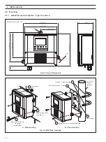
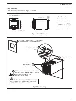
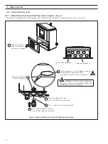
– a case earth (ground) stud is fitted to the analyzer case for bus-bar earth (ground) connection – see
Fig. 6.8 (wall-/pipe-mount analyzers) or Fig. 6.10 (panel-mount analyzers).
•
Cable routing
– always route signal output/pH electrode cable leads and mains-carrying/relay cables separately, ideally in
earthed metal conduit. Use twisted pair output leads or screened cable with the screen connected to the case earth (ground)
stud.
Ensure that the cables enter the analyzer through the glands nearest the appropriate screw terminals and are short and direct.
Do not tuck excess cable into the terminal compartment.
•
Cable glands & conduit fittings
– ensure that the NEMA4X/IP66 rating is not compromised when using cable glands, conduit
fittings and blanking plugs/bungs (M20 holes). The M20 glands accept cable of between 5 and 9mm (0.2 and 0.35 in.) diameter.
•
Relays
– the relay contacts are voltage-free and must be appropriately connected in series with the power supply and the
alarm/control device which they are to actuate. Ensure that the contact rating is not exceeded. Refer also to Section 6.3.1 for
relay contact protection details when the relays are to be used for switching loads.
•
Analog output
– Do not exceed the maximum load specification for the selected analog output range
.
Since the analog output is isolated, the –ve terminal
must
be connected to earth (ground) if connecting to the isolated input
of another device.
…6
INSTALLATION


