


4
…2
OPERATION
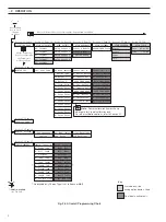
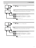
Use the Menu
Key to scroll
through
the Menus
Available only if the
analog option board is fitted
Key
VIEW SETPOINTS
VIEW OUTPUTS
VIEW HARDWARE
VIEW SOFTWARE
A1: Setpoint
Analog Output 1
Sensor A Module
AX400/2000 Issue
A2: Setpoint
Analog Output 2
Sensor B Module
A3: Setpoint
Analog Output 3
Option Board
A4: Setpoint
Analog Output 4
A5: Setpoint
Security Code
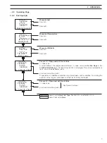
SENSOR CAL.
Cal. User Code
Sensor Cal. A
A: Buffer Method
A: Immerse Buf.1
A: Cal. Buffer 1
A: Immerse Buf.2
A: Cal. Buffer 2
A: Calibration
CONFIG.SENSORS
B: Probe Type
B: Diff. Input
B: Electrode
B: Temp. Comp
B: Temp. Sensor
B: Preset Temp.
B: Sample Comp.
CONFIG. DISPLAY
Set Language
Set Temp. Units
Set Backlight
LED Backlight
Temp. Units
English
B: Sample Coeff.
Use the Sidescroll Key to scroll through the Pages within each Menu
To
CONFIG. ALARMS
(see Fig. 2.3B)
Use the Downscroll
Key to scroll through
the Parameters
within each Page
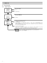
OPERATING PAGE
Section 2.3, Page 6
Section 3.1, Page 12
Section 3.2, Page 13
Section 3.3, Page 13
Section 3.4, Page 14
Section 3.5, Page 14
Section 4.1, Page 18
Section 5.1, Page 25
Section 5.2, Page 26
Section 5.3, Page 27
Section 3.6, Page 17
Set Auto Buffers
Buffer Type
Set Buffer 1
Set Buffer 2
A: Slope & Check
Sensor Cal. B
B: Buffer Method
B: Immerse Buf.1
B: Cal. Buffer 1
B: Immerse Buf.2
B: Cal. Buffer 2
B: Calibration
B: Slope & Check
B: Set Min Slope
Config. Sensor B
Config. Sensor A
A: Probe Type
A: Diff. Input
A: Temp. Comp
A: Temp. Sensor
A: Preset Temp.
A: Sample Comp.
A: Sample Coeff.
A: Set Min Slope
A: Electrode
A: Enter Point 1
A: Enter Point 2
B: Enter Point 1
A: Enter Point 5
A: Enter Point 4
A: Enter Point 3
B: Enter Point 2
B: Enter Point 5
B: Enter Point 4
B: Enter Point 3
#### 100% ####
#### 100% ####
#### 100% ####
#### 100% ####
Alarms
Errors
Power
Cals
VIEW LOGBOOK
Dual input analyzer only
VIEW CLOCK
Date
01:01:03
Time
12:00
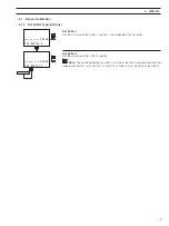
Note.
Sensor calibration frames shown
above are for 2-point calibration only.
For other calibration options, refer to Section 4.1.
A: Enable Cals
B: Enable Cals
*
*
*
Applicable only if
Probe Type
is set to
Redox
or
ORP
Fig. 2.3A Overall Programming Chart


