


49
Notes.
•
The analyzer is calibrated by the Company prior to dispatch and routine recalibration is not necessary. High stability
components are used in the analyzer's input circuitry and, once calibrated, the Analog to Digital converter chip self-
compensates for zero and span drift. It is therefore unlikely that the calibration will change over time. It is not advisable to
attempt recalibration unless the input board has been replaced or the calibration tampered with.
•
Prior to attempting recalibration, test the analyzer's accuracy using suitably calibrated test equipment – see Sections 7.2 and
7.3.
7.1
Equipment Required
a) Millivolt source (pH or Redox input simulator): –1000 to 1000 mV.
b) Decade resistance box (Pt100/Pt1000 temperature input simulator): 0 to 1k
Ω
(in increments of 0.01
Ω
), accuracy
±
0.1%.
c) Digital milliammeter (current output measurement): 0 to 20mA.
Note.
Resistance boxes have an inherent residual resistance which may range from a few m
Ω
up to 1
Ω
. This value must
be taken into account when simulating input levels, as should the overall tolerance of the resistors within the boxes.
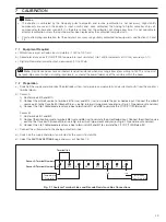
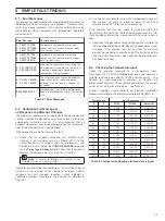
7.2
Preparation
a) Switch off the supply and disconnect the electrode system, temperature compensator(s) and current output(s) from the analyzer's
terminal blocks.
b) Sensor A:
1) Link terminals B9 and B10.
2) Connect the millivolt source to terminals B16 (+ve) and B14 (–ve) to simulate the pH or Redox input. Connect the millivolt
source earth to the Case Earth (Ground) Stud – see Fig. 6.8 (wall-/pipe-mount analyzer) or Fig. 6.10 (panel-mount analyzer).
4) Connect the 0 to 10k
Ω
decade resistance box to terminals B11 and B9 to simulate the
Pt100/Pt1000
/Balco 3K.
Sensor B:
1) Link terminals B1 and B2.
2) Connect the millivolt source to terminals B8 (+ve) and B6 (–ve) to simulate the pH or Redox input. Connect the millivolt source
earth to the Case Earth (Ground) Stud – see Fig. 6.8 or (wall-/pipe-mount analyzer) or Fig. 6.10 (panel-mount analyzer).
4) Connect the 0 to 10k
Ω
decade resistance box to terminals B3 and B1 to simulate the
Pt100/Pt1000
/Balco 3K.
c) Connect the milliammeter to the analog output terminals.
d) Switch on the supply and allow ten minutes for the circuits to stabilize.
d) Select the
FACTORY SETTINGS
page and carry out Section 7.3.
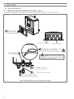
Fig. 7.1 Analyzer Terminal Links and Decade Resistance Box Connections
Terminal link
pH/Redox
Input Simulator
Temperature
Simulator
B10
B11
B12
B13
B14
B9
Sensor A Terminal Numbers
Sensor B Terminal Numbers
B2
B3
B4
B5
B6
B1
B15
B16
B7
B8
–ve
+ve
7
CALIBRATION


