


46
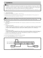
Terminal block A
Terminal Block B
Terminal Block C
(Analog Option Board)
C1
C2
C3
C4
C5
C6
Earth (Gr
ound)
C7
C
C8
NC
Relay 4
C9
NO
C10
C
C11
NC
Relay 5
C12
NO
C13
+
Analog Output 3
C14
—
C15
+
Analog Output 4
C16
—
Temperature Compensator
Connections
Line
L
Neutral
N
Earth (Gr
ound)
E
CA
4
Relay 1
N
C
A
5
NO
A6
CA
7
Relay 2
N
C
A
8
NO
A9
C
A10
Relay 3
N
C
A11
NO
A12
Analog Output 1
+
A13
—
A14
Analog Output 2
+
A15
—
A16
B16
B15
B14
B13
B12
B11
B10
B9
B8
B7
B6
B5
B4
B3
B2
B1
TC
Thir
d Lead
Common
TC
Thir
d Lead
Common
Temperature Compensator
Connections
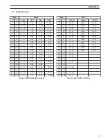
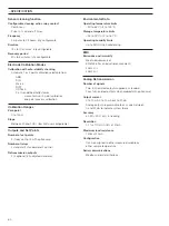
* If fitted
** When a 2-wire Pt100, Pt1000 or 'Balco 3K' temperature compensator is fitted.
*** Solution Earth also referred to as Ground Rod.
TC = Temperature Compensator.
Terminal Block B
pH/Redox (ORP)
without solution earth
(standard input)
Sensor B
Sensor A
1
9
TC Common*, Link 1 & 2/9 & 10**
2
10
TC Third Lead*
3
11
TC
4
12
N/A
5
13
Reference Electrode
6
14
Screen*
7
15
Not Used
8
16
Glass/Metal Electrode
TC Common*, Link 1 & 2/9 & 10**
pH/Redox (ORP)
with solution earth
(differential input)
TC Third Lead*
TC
Screen*
Not Used
Reference Electrode
Glass/Metal Electrode
Solution Earth***
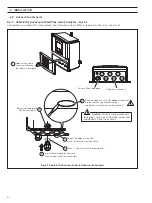
…6
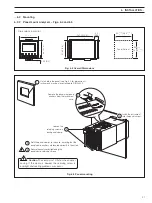
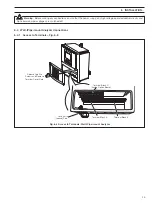
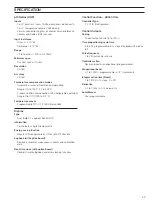
INSTALLATION
…6.4
Wall-/Pipe-mount Analyzer Connections
6.4.2
Connections – Fig. 6.9
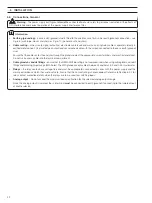
Note.
Relay 3 can be configured to control the wash facility – see Section 5.4.
Fig. 6.9 Connections, Wall-/Pipe-mount Analyzer


