
6/1531-ANF 901 14 Uen F1 2013-11-29
55
A
PPENDIX
A
9.2 Technical
data
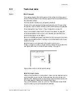
9.2.1 ELU31
board
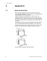
The building height of ELU31 board is 20 mm. When the front plate is
removed from the ELU31 board and a support front is mounted it fits into
the stackable cabinet.
The base station interface is a proprietary interface.
The ELU31 board supplies the base stations with -48 V. Power is fed
through the communication interface and the EPP interface if applicable.
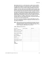
Power dissipation: See Table 7, Power dissipation on page 48
Power consumption: See Table 8, Power consumption on page 48
In some backplanes there are two -48 V feeding pins and there the
power consumption can be higher.
ELU31/3, FW R7B and greater, and ELU31/4 has improved ring commu-
nication and ACDM function. Therefor is it recommended to use these
board in the ring.
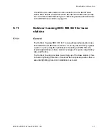
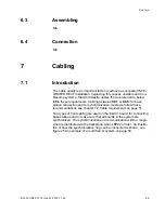
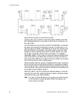
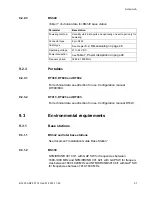
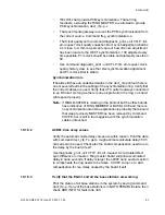
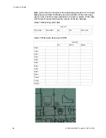
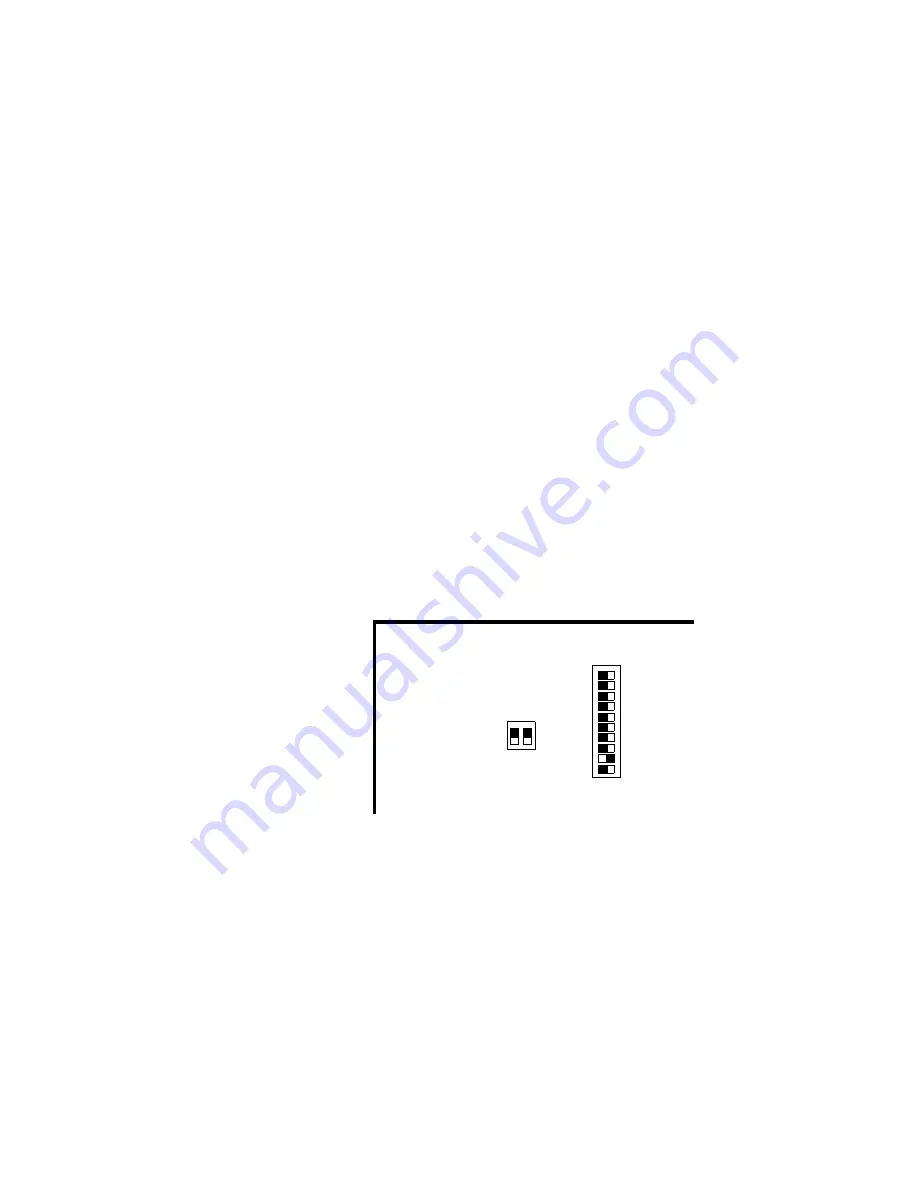
ELU31/4 has an on-board switch.The switch can be set to
“index_3_mode” or “index_4_mode”. How to change mode on ELU31/4,
see figure 28 ELU31/4 on-board switch setting. on page 55.
Figure 28:ELU31/4 on-board switch setting.
ELU31/4 index 4 mode.
When all ring boards are running index 4 mode can ring members act as
synchronization source for the media gateway, like any primary rate
interface (E1). Master board can not act as a synchronization source for
the media gateway. Master board shall always have
‘trsp_synchronization --class no --prio no’. That is Master board shall
never be able to give synchronization to its MGU.
/3
/4
both switches in lower position
i.e. index 3 mode
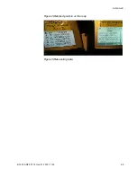
ELU31 upper left corner


