C
ORDLESS
P
HONE
32
6/1531-ANF 901 14 Uen F1 2013-11-29
5.9
Mounting of base station BS3x0 and BS3x2
5.9.1 General
The base station is connected to the ELU31 board by means of a stan-
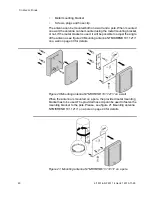
dard twisted pair cable. The base station can be fixed to a wall, a ceiling,
a pole or a beam, by means of the mounting bracket included. When
fixing the base station to a wall or ceiling the included plugs and screws
must be used. When fixing it to a pole or beam a (not included) strap.
Content of the box.
See chapter “BS3x0” or “BS3x2” in “Installation Guide Base Station”.
Power distribution
Base stations can be powered by:
•
SC0 and SC1 pairs from the ELU31 boards.
•
SC0 and SC1 pairs and Express Powering Pairs (EPP) from the
ELU31 boards.
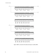
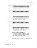
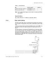
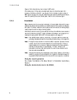
For cabling see figure 16 Connections when using 2 EPP pairs on page
34 and chapter 6.2 Dimensioning on page 46.
Software
If necessary, the software in the base station can be updated by down-
loading new software to the base station. Downloading can be
performed without disconnecting the base stations. The new software is
stored in a flash memory. How to download the software is described in
the command descriptions for
BOARD CONFIGURATION
.
Connectors
Two 8-pin RJ45 modular jacks for data and powering.
A 6-pin RJ12 modular jack for factory testing.
The two data/powering connectors are interconnected on the board.
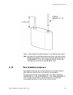
Two female MCX connectors for the antennas (BS340 only)
Orderable items (Only applicable for BS34x
)
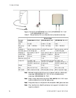
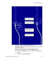
For outdoor applications and applications requiring special antenna
arrangement, there is a possibility to connect non-standard antennas to
the BS34x. For external antennas, one of the following non-standard
antennas can be used.


