


C
ORDLESS
P
HONE
34
6/1531-ANF 901 14 Uen F1 2013-11-29
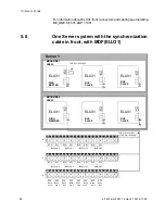
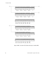
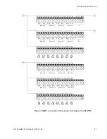
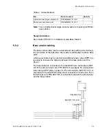
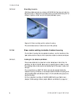
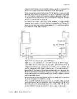
Figure 16:Connections when using 2 EPP pairs
The data wires of the same twisted pair may be interchanged. For
instance SC0-0 and SC0-1, see figure 16 Connections when using 2
EPP pairs on page 34, may be interchanged. Also the EPP pair is insen-
sitive for polarity reversal. Data pairs must not be interchanged.
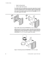
5.9.3 Installation
Base stations can be mounted vertically or horizontally. Mount the base
stations at places and positions as determined in the system configura-
tion plan. The base station must be placed such that it is not facing large
metal objects such as large heating pipes.
With the Outdoor housing (a weatherproof box) the BS33x base station
can be mounted to a wall or a pole outside of buildings, see chapter 5.11
Outdoor housing SDC 905 04/1 for base stations on page 41
Note:
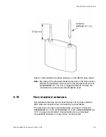
The BS34x base station cannot be mounted with the antennas
pointing downwards as the mounting bracket does not support it.
Note:
Fixing the base station to metal surface requires special consid-
eration and is not recommended for several reasons. if this is
unavoidable try to ensure a distance between the base station
and the metal surface of, preferably, 1 meter. If this is not
possible to achieve the best option to use is base station with
internal antennas/BS330.
Note:
Ensure that during the installation of an base station, each base
station is given an extra length (5-10 metres) of cable because it
is possible that it will have to be moved for one reason or another.
Fixing the mounting bracket
See chapter “Installation of the Base Station” in “Installation Guide Base
Station”.
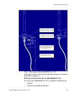
Fixing the standard antennas to the BS340.


