Chapter 24 Multicast
GS2210 Series User’s Guide
208
24.5.2 MVR Configuration Example
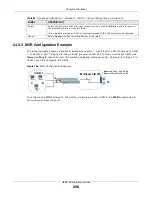
The follow ing figur e show s a net w or k exam ple w her e por t s 1, 2 and 3 on t he Swit ch belong t o VLAN
1. I n addit ion, por t 7 belongs t o t he m ult icast gr oup w it h VI D 200 t o r eceive m ult icast t raffic ( t he
N e w s and M ov ie channels) fr om t he r em ot e st r eam ing m edia ser ver, S. Com put er s A, B and C in
VLAN 1 ar e able t o r eceive t he t raffic.
Figure 146
MVR Configurat ion Ex am ple
To configur e t he MVR set t ings on t he Sw it ch, cr eat e a m ult icast VLAN in t he M V R scr een and set
t he r eceiver and sour ce por t s.
Delet e
Select t he ent r y ( ies) t hat you w ant t o rem ove, t hen click t he D e le t e but t on t o r em ove
t he select ed ent r y( ies) fr om t he t able.
I f you delet e a m ult icast VLAN, all m ult icast gr oups in t his VLAN w ill also be r em oved.
Cancel Select
Ca n ce l t o clear t he check box ( es) in t he t able.
Table 90
Advanced Applicat ion > Mult icast > MVR > Gr oup Configur at ion ( cont inued)
LABEL
DESCRIPTION
S
Multicast VID 200
VLAN 1
A
B
C
News: 224.1.4.10 ~ 224.1.4.50
1
Movie: 230.1.2.50 ~230.1.2.60
2
3
7

