R800
HANDBOOK
17
5. R
OUTER
C
ONFIGURATION
About this Chapter
Sections
Description
Overview
In this section, you can know that R800 LTE Router configuration can be realized in a WEB-based method.
Basic Configuration
In this section, you can know the basic configuration operations to be completed before advanced configuration of
R800 LTE Router.
Application Configuration
In this section, you can know what is included in application configuration of R800 LTE Router and how to operate
configurations.
VPN Configuration
In this section, you can know VPN functions of R800 LTE Router and how to operate configurations.
Forwarding Configuration
In this section, you can know the forwarding configurations of R800 LTE Router and how to operate configurations.
Security Configuration
In this section, you can know the security configurations of R800 LTE Router and how to operate configurations.
System Management
Configuration
In this section, you can know the system management configurations of R800 LTE Router and how to operate
configurations.
Status
In this section, you can know the items of status inquiry and how to carry out status inquiry.
Function of RESET
In this section, you can know the functions of RESET of R800 LTE Router and how to use it.
5.1. Overview
R800 LTE Router configuration can be done in a WEB-based manner. Configuration in a WEB-based manner is simple and direct.
After local area connection of PC with R800 LTE Router is completed according to
“
4.2 Local Area Connection Configuration
”
,
chrome browser can be started; login to R800 LTE Router for configuration.
Chrome browser is highly recommended. If you use other browsers, some pages may not make appearance.
5.2. Basic Configuration
Do as per
”
5.2.2 Network Configuration
”
, and you can have dial-up access and have access to public network.
5.2.1. L
OGIN TO
WEB C
ONFIGURATION
I
NTERFACE
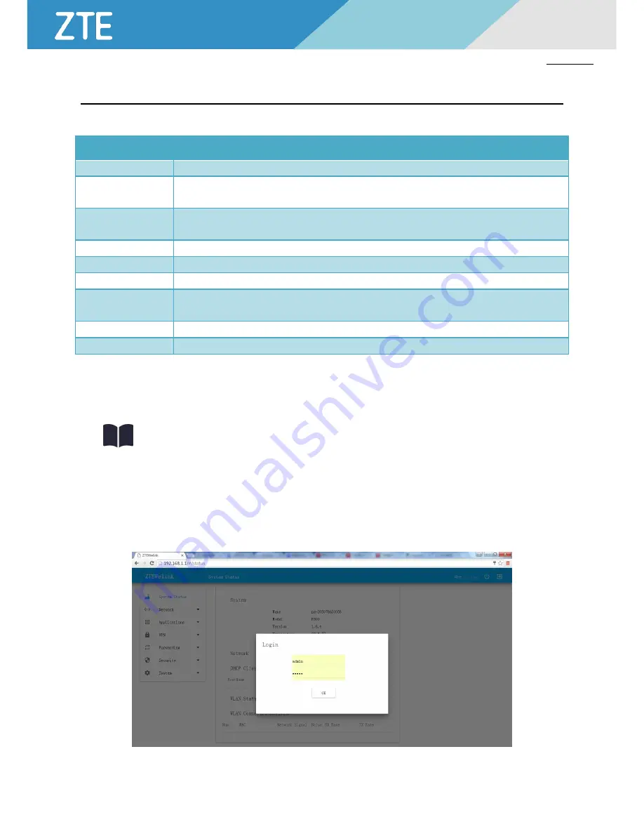
Step 1 Start chrome browser of configuration computer, and insert http://192.168.1.1/ in the address field. Enter the user
Login ID authentication interface. See Figure 5-2-1.
Figure 5-2-1 User Login ID Authentication Interface


