17
Smooth Radius
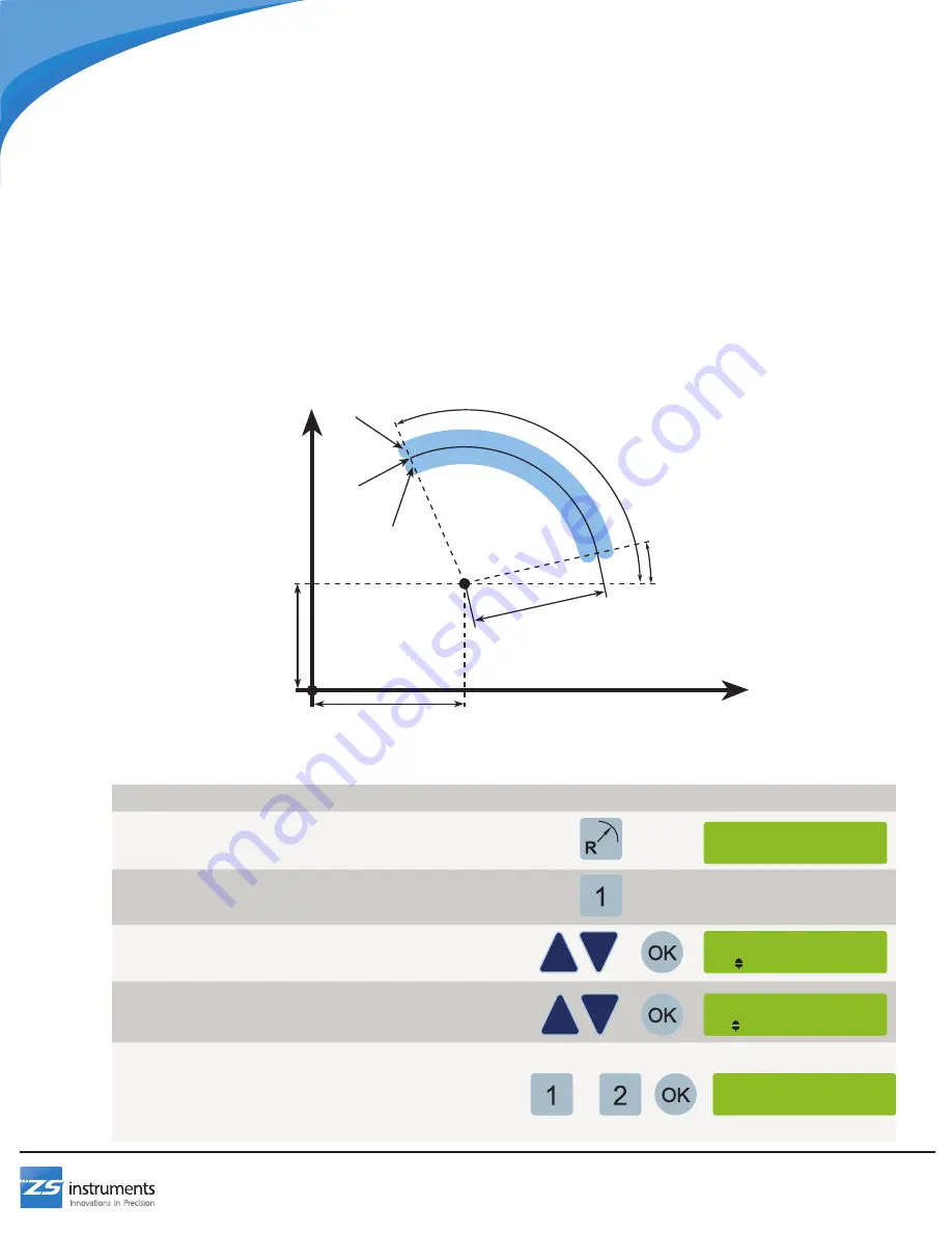
To machine a radius or rounded feature in any plane, use the Smooth Radius feature. When machining a Smooth Radius
feature the digital readout will sequentially display the coordinates of the two axes where the tool needs to be positioned
to create the curved surface. This program requires the following inputs:
• The cut plane of the radius (XY, YZ, or XZ)
• Whether the cut will be external or internal
• The position of the center point of the radius
• The starting and ending angles (counterclockwise from the three o’ clock position)
• The radius of the feature
• The maximum cut size (smaller number produces smoother result but requires more machining steps)
The Smooth Radius feature can be saved to one of 99 slots or it can be run immediately without saving
Note: A ball end mill MUST be used when milling radii on the XZ or YZ planes.
To Create a New Smooth Radius Feature:
Step
Buttons
Information Screen
1 Press the radius button to access the smooth radius
feature
2 Press 1 to setup a new smooth radius program
3 Select a cut plane using the up and down arrows, then
press OK to confirm
4 Use the up and down arrows to select whether the cut
will be internal or external
Press OK to confirm
5 Enter the center point of the radius for each axis:
Press 1 to sense the current position
OR
Press 2 to enter the position using the numpad
Press OK to confirm
*SMOOTH RADIUS*
1-New 2-Load
Cut Plane
1 XY
Cut direction
1 External
Mill Functions
X Center
Y Center
Start Angle
End Angle
Radius
External
Cut
Internal
Cut
Edge of Cut
Y Axis
X Axis
Datum
OR
X Center
1-Sense 2-Enter


