4-5
4.4 Auxiliary Power System
In the event that the main power is not working, the auxiliary power system is used as an alternative to
take the operator away from the height of the work to the safe ground. This system uses an electric
motor/pump unit powered by a 12V battery. The auxiliary power system is not intended to be used as
the primary power source. The auxiliary power system allows all functional units to return to the stowed
or lowered state and supports the jib lifting. The auxiliary power system keeps the work platform in a
horizontal position when the boom is lowering. The auxiliary power system does not support the driving
function.
4.5 Oscillating axle system
The oscillating front axle is mounted to the frame by a pivot pin that allows the four wheels to remain in
contact with the ground traveling over rough terrain. The oscillating axle system also includes two
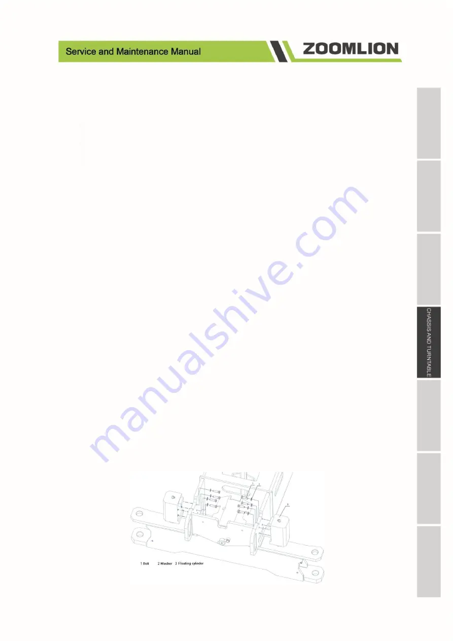
floating cylinders for connecting the frame to the front axle. The floating cylinder allows the front axle
to oscillate when the boom is retracted in transit. When the boom is extended by 1,000 mm/3.28ft or the
boom angle is more than 7° with respect to the horizontal level, the floating cylinder will keep the front
axle in its original position and prevent it from swinging.
The ground controller monitors the boom angle by installing an angle sensor at the end of upper boom.
The ground controller monitors the boom extension by a wire sensor mounted on the inside of the boom.
When the ground controller detects that the condition for releasing the front axle lock is satisfied, the
controller sends a pilot pressure to the floating cylinder. The pilot pressure is provided by driving the
pump charge pressure. When the pilot pressure is applied to the balancing valve mounted on the floating
cylinder, the front axle is unlocked, and when the pilot pressure is released, the front axle is locked. The
first lock compound valve is normally closed, and it opens when oil flows into the floating cylinder. The
second valve is connected to the tank and is located between the first valve and the floating cylinder. It
closes when it blocks the oil return to the tank or the oil flowing to the floating cylinder. Any of these
valves are in their normal state, the front axle should be locked. The ground control provides power and
monitors the boom angle sensor and wire sensor. If the status of the sensor is inconsistent, the ground
control will cut off the power supply, which will cause the swing front axle to lock in an unsafe state
until it is re-powered.
Figure 4-4 Floating cylinder disassembly diagram
Summary of Contents for ZT20J
Page 8: ......
Page 9: ......
Page 17: ......
Page 18: ......
Page 25: ......
Page 26: ......
Page 43: ......
Page 44: ......
Page 58: ......
Page 59: ......
Page 83: ......
Page 84: ......
Page 96: ......
Page 97: ......
Page 105: ...7 8 Figure 7 11 Electrical Schematics Figure 1 6 Perkins engine ...
Page 106: ...7 9 Figure 7 12 Electrical Schematics Figure 1 6 Deutz D447 engine ...
Page 107: ...7 10 Figure 7 13 Electrical Schematics Figure 1 6 Deutz D2 9 engine ...
Page 108: ...7 11 Figure 7 14 Electrical Schematics Figure 2 6 ...
Page 109: ...7 12 Figure 7 14 Electrical Schematics Figure 3 6 ...
Page 110: ...7 13 Figure 7 16 Electrical Schematics Figure 4 6 ...
Page 111: ...7 14 Figure 7 17 Electrical Schematics Figure 5 6 ...
Page 112: ...7 15 Figure 7 18 Electrical Schematics Figure 6 6 ...
Page 113: ...7 16 7 5 Hydraulic Schematics Figure 7 19 Hydraulic Schematics Figure ...


