DDOC00247
enu / 2018-09-14 / Index a
INSTALLATION AND OPERATING INSTRUCTIONS:
Pneumatic gripper, intelligent GPP/GPD5000IL series
Zimmer GmbH
●
Im Salmenkopf 5
●
77866 Rheinau, Germany
●
Phone: +49 7844 9138-0
●
Fax: +49 7844 9138-80
●
www.zimmer-group.de
7. Commissioning
6
7.1
IO-LINK commissioning
Pin
Color
Function
Explanation
1
Brown
+24V DC sensor
Power supply for IO-Link communication
2
White
+24V DC actuator
Actuator supply voltage
3
Blue
GND sensor
Sensor 0 V DC supply voltage
4
Black
C/Q
IO-Link communication
5
Gray
GND actuator
Actuator 0 V DC supply voltage
► Connecting the gripper to the IO-Link master
► Ensuring the supply voltage (for Port Class A additional supply via Y-cable)
NOTE:
For details on the tightening torque, screw diameter and maximum weight and length of the gripper fingers, refer to
the product data sheet
.
Many different non-conductive parts move around in the gripper. As a consequence, high voltages can arise as a result of
electrostatic charges, which can also discharge to the component. If this is not desired, it must be ensured that the gripper can be
discharged of electrostatic charges via its mounting surface.
6.4
Static charge
NOTE:
Grounding the gripper attachment is recommended if parts sensitive to electrostatic discharge come into contact
with the gripper.
Before installing the gripper fingers, make sure they are of a suitable length for the selected gripper variant.
The following work steps should be performed to install the gripper fingers:
► Insert centering sleeves into the provided matching parts on the gripper jaws
► Position the gripper fingers on the gripper jaws using the centering sleeves
► Secure the gripper fingers using cylinder screws with strength class of at least 8.8
6.3
Installing the gripper fingers
6.5
Influencing the position sensor
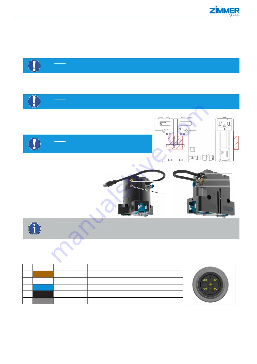
In the adjacent figure, an area in which no magnets or components with
ferromagnetic properties may be fastened is marked.
This can have a significant influence on accuracy of the position sensor and/
or result in a malfunction of the position sensor.
NOTE:
The position sensor itself must never be covered up by fer-
romagnetic attachment or design elements.
6.6
Pneumatic connection
7
Connection "R": Exhaust air with
mounted silencer
8
Connection "S": Exhaust air with
mounted silencer
9
Connection "P": Compressed air
8
7
9
INFORMATION:
The pneumatic connections A and B right on the gripper are not used and are closed.
For applications with an IP64 protection class, we recommend installing hoses on the "R" and "S" connections
for diverting the exhaust air to prevent the condensate from damaging the silencers.
8
9
7


